


12 / 36 - Español
6-1622396 - rev. 3 - 21/09/2021
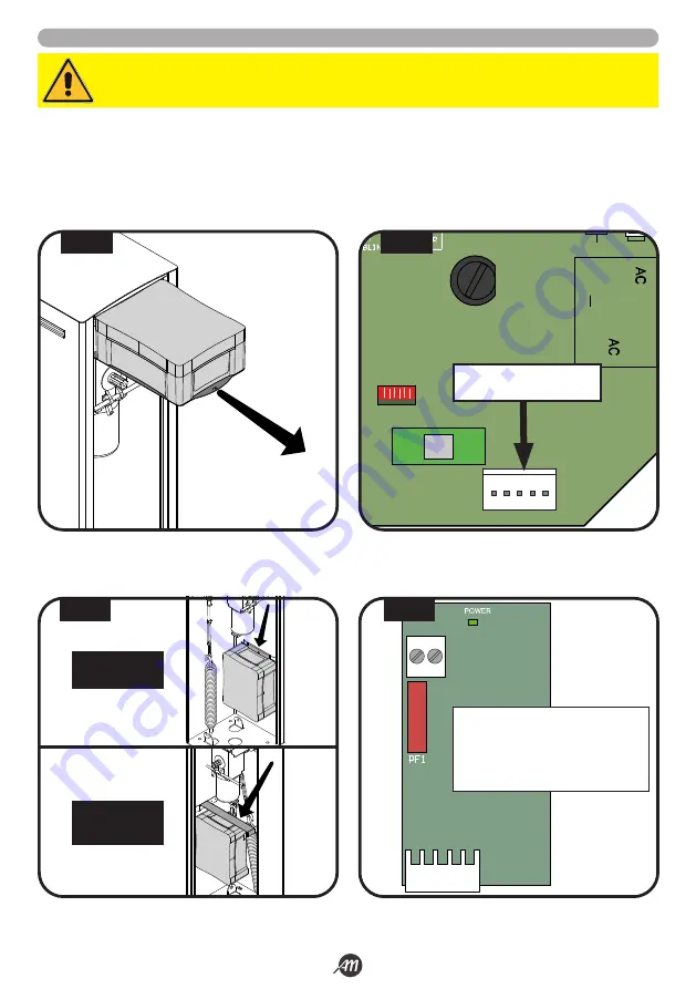
5.4 INSTALACIÓN KIT DE BATERÍA (OPCIONAL)
1.
Extraiga la caja del controlador y quite la tapa desenroscando los tornillos adecuados (Fig.17).
2.
Instalar la tarjeta de interfaz de baterías en el asiento dedicado de la unidad de control (Fig.18).
3.
Colocar la caja de baterías enganchándola a los soportes colocados en el interior del armario y hacer pasar los cables a través
del pasacables de la caja de la centralita (Fig.19).
4.
Conecte los cables de la caja a la tarjeta de interfaz de baterías (Fig.20).
ATENCIÓN!
Asegúrese de que la tarjeta no se enciende antes de hacer los enlaces.
+ -
J2
Descripción:
+
terminal positivo BATERÍA
-
terminal negativo BATERÍA
PF1
Fusible T 10A
J2
Conector de acoplamiento
1
LED RADIO
FUSE 1
FUSE 2
J2
J1
J3
2
3
4
5
6
7
8
9 10
11 12 13 14 15 16 17
20 21
LED STATUS
LED STATUS
J4
CONECTOR TARJETA DE
INTERFAZ BATERÍAS
FIG. 17
FIG. 18
FIG. 19
FIG. 20
VERSIÓN 4
METROS
VERSIÓN 6
METROS
Summary of Contents for 12007336
Page 15: ...Italiano 15 36 6 1622396 rev 3 21 09 2021 45 45 1 2 3 1 2 3 FIG 27 FIG 28...
Page 51: ...English 15 36 6 1622396 rev 3 21 09 2021 45 45 1 2 3 1 2 3 FIG 27 FIG 28...
Page 87: ...Fran ais 15 36 6 1622396 rev 3 21 09 2021 45 45 1 2 3 1 2 3 FIG 27 FIG 28...
Page 123: ...Espa ol 15 36 6 1622396 rev 3 21 09 2021 45 45 1 2 3 1 2 3 FIG 27 FIG 28...
Page 159: ...Nederlandse 15 36 6 1622396 rev 3 21 09 2021 45 45 1 2 3 1 2 3 FIG 27 FIG 28...


