


Nederlandse - 11 / 36
6-1622396 - rev. 3 - 21/09/2021
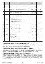
5.3 INSTALLATIE MET LED-KIT (OPTIONEEL) - ALLEEN VOOR 4 METER VERSIE
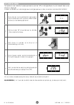
1.
Schuif de lade met besturingskast uit de behuizing en verwijder de deksel door de schroeven los te draaien (Fig.13).
2.
Plaats de LED-interfacekaart in de juiste sleuf (In de BOOMY 4 LED-versie is de kaart al geïnstalleerd) (Fig.14).
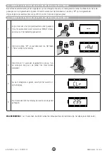
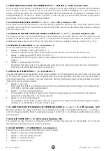
3.
Boor twee gaten met een diameter van 6 mm op het zwarte plastic dop die de onderkant van de boom / mast bedekt (Fig.15).
4.
Voer de LED-voedingskabels door de zojuist gemaakte gaten, door het kabelgat van de kast en door het kabelgat van de
bedieningskast.
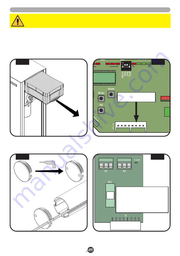
5.
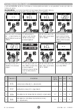
Sluit de LED strips aan op de LED kaart (Fig.16).
WAARSCHUWING!
Zorg ervoor dat de kaart niet van stroom wordt voorzien voordat u de aansluitingen tot stand brengt.
G
R +24
G
R +24
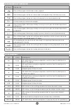
Beschrijving:
G
LED-kanaal GROEN
R
LED-kanaal ROOD
+24
LED-v24 Vdc
PF1
Fuse T 1A
J1 INSTEEKCONNECTOR
1
LED RADIO
FUSE 1
FUSE 2
J2
J1
J3
2
3
4
5
6
7
8
9 10
11 12 13 14 15 16 17
20 21
LED STATUS
LED STATUS
J4
SLEUF VOOR DE LED
INTERFACEKAART
2 x Ø 6mm
FIG. 13
FIG. 14
FIG. 15
FIG. 16
Summary of Contents for 12007336
Page 15: ...Italiano 15 36 6 1622396 rev 3 21 09 2021 45 45 1 2 3 1 2 3 FIG 27 FIG 28...
Page 51: ...English 15 36 6 1622396 rev 3 21 09 2021 45 45 1 2 3 1 2 3 FIG 27 FIG 28...
Page 87: ...Fran ais 15 36 6 1622396 rev 3 21 09 2021 45 45 1 2 3 1 2 3 FIG 27 FIG 28...
Page 123: ...Espa ol 15 36 6 1622396 rev 3 21 09 2021 45 45 1 2 3 1 2 3 FIG 27 FIG 28...
Page 159: ...Nederlandse 15 36 6 1622396 rev 3 21 09 2021 45 45 1 2 3 1 2 3 FIG 27 FIG 28...


