


English - 11 / 36
6-1622396 - rev. 3 - 21/09/2021
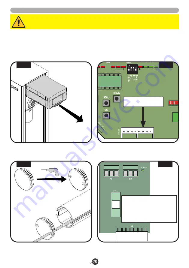
5.3 INSTALLATION WITH LED KIT (OPTIONAL) - ONLY FOR 4 METERS VERSION
1.
Take out the box of the control unit and remove the lid by unscrewing the screws (Fig.13).
2.
Install the LED interface card in the appropriate slot (in the BOOMY 4 LED version the card is already installed) (Fig.14).
3.
Drill two Ø 6 mm holes on the black plastic cap that covers the bottom of the boom (Fig.15).
4.
Pass the LED power cables through the holes just made, through the cable hole of the cabinet and through the cable hole of
the control box.
5.
Connect the led strips to the led card (Fig.16).
WARNING!
Make sure the board is not powered before making connections.
G
R +24
G
R +24
Description:
G
LED channel GREEN
R
LED channel RED
+24
LED power 24Vdc
PF1
Fuse T 1A
J1
PLUG-IN connector
1
LED RADIO
FUSE 1
FUSE 2
J2
J1
J3
2
3
4
5
6
7
8
9 10
11 12 13 14 15 16 17
20 21
LED STATUS
LED STATUS
J4
SLOT FOR THE LED
INTERFACE BOARD
2 x Ø 6mm
FIG. 13
FIG. 14
FIG. 15
FIG. 16
Summary of Contents for 12007336
Page 15: ...Italiano 15 36 6 1622396 rev 3 21 09 2021 45 45 1 2 3 1 2 3 FIG 27 FIG 28...
Page 51: ...English 15 36 6 1622396 rev 3 21 09 2021 45 45 1 2 3 1 2 3 FIG 27 FIG 28...
Page 87: ...Fran ais 15 36 6 1622396 rev 3 21 09 2021 45 45 1 2 3 1 2 3 FIG 27 FIG 28...
Page 123: ...Espa ol 15 36 6 1622396 rev 3 21 09 2021 45 45 1 2 3 1 2 3 FIG 27 FIG 28...
Page 159: ...Nederlandse 15 36 6 1622396 rev 3 21 09 2021 45 45 1 2 3 1 2 3 FIG 27 FIG 28...


