


12 / 36 - English
6-1622396 - rev. 3 - 21/09/2021
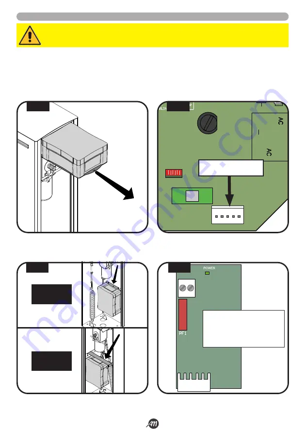
5.4 BATTERY KIT INSTALLATION (OPTIONAL)
1.
Take out the box of the control unit and remove the lid by unscrewing the screws (Fig.17).
2.
Install the card battery interface in the appropriate slot (Fig.18).
3.
Place the battery box by attaching it to the supports inside the cabinet and pass the cables through the cable hole of the
control box (Fig.19).
4.
Connect the cables coming from the box to the card of battery interface (Fig.20).
WARNING!
Make sure the board is not powered before making connections.
+ -
J2
Description:
+
BATTERY positive pole
-
BATTERY negative pole
PF1
Fuse T 10A
J2
PLUG-IN connector
1
LED RADIO
FUSE 1
FUSE 2
J2
J1
J3
2
3
4
5
6
7
8
9 10
11 12 13 14 15 16 17
20 21
LED STATUS
LED STATUS
J4
BATTERY CHARGER
CARD SLOT
FIG. 17
FIG. 18
FIG. 19
FIG. 20
4 METERS
VERSION
6 METERS
VERSION
Summary of Contents for 12007336
Page 15: ...Italiano 15 36 6 1622396 rev 3 21 09 2021 45 45 1 2 3 1 2 3 FIG 27 FIG 28...
Page 51: ...English 15 36 6 1622396 rev 3 21 09 2021 45 45 1 2 3 1 2 3 FIG 27 FIG 28...
Page 87: ...Fran ais 15 36 6 1622396 rev 3 21 09 2021 45 45 1 2 3 1 2 3 FIG 27 FIG 28...
Page 123: ...Espa ol 15 36 6 1622396 rev 3 21 09 2021 45 45 1 2 3 1 2 3 FIG 27 FIG 28...
Page 159: ...Nederlandse 15 36 6 1622396 rev 3 21 09 2021 45 45 1 2 3 1 2 3 FIG 27 FIG 28...


