


English - 21 / 36
6-1622396 - rev. 3 - 21/09/2021
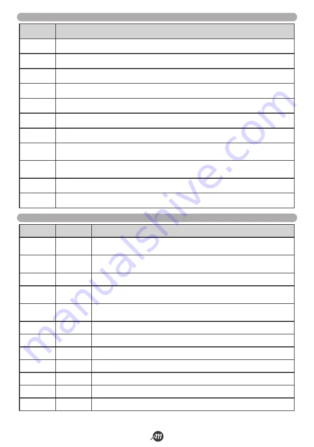
DISPLAY
DESCRIZIONE
RAD
It is displayed while learning transmitters.
don
It is displayed when a new transmitter is learned or at the end of a reset.
Fnd
It is displayed when a button is learned from an already learned transmitter.
CLR
Appears when a transmitter is deleted.
LOP
It is displayed during the learning of the strokes to indicate that the central is opening.
LCL
It is displayed during the learning of the strokes to indicate that the central is closing.
L--
It is displayed during the learning of the strokes in case of intervention of a security.
sEE
It is displayed when the control panel is waiting for a signal from a transmitter during the display of the
memory location (
trS
function).
Not
It is displayed when the transmitter is not present in memory during the display of the memory location (
trS
function).
tout
It is displayed when the control panel exits due to inactivity from the display of the memory position.
power
It is displayed when the supply voltage is not enought.
9.3 ALERTS DURING OPERATION
LED
COLOUR
DESCRIPTION
PH1
RED
Led normally on in case of input connected to an NC contact. Signal the activation of the
photocell PH1.
PH2
RED
Led normally on in case of input connected to an NC contact. Signal the activation of the
photocell PH2.
PH3
RED
Safety signal, LED normally on.
S1
RED
Led normally on in case of input connected to an NC contact. Signal the activation of the
loop detector S1.
S2
RED
Led normally on in case of input connected to an NC contact. Signal the activation of the
loop detector S2.
S3
RED
Safety signal, LED normally on.
STOP
RED
Safety signal, LED normally on.
OPEN
GREEN
Led normally off. It is switched on when it receives opening command.
CLOSE
GREEN
Led normally off. It is switched on when it receives closing command.
SS
GREEN
Led normally off. It is switched on when it receives step-by-step command.
RADIO
RED
Led switched on in the presence of a radio transmission or interference.
POWER ON
GREEN
Led normally on. Indicates the presence of input voltage to the control unit.
9.4 LED ALERTS
Summary of Contents for 12007336
Page 15: ...Italiano 15 36 6 1622396 rev 3 21 09 2021 45 45 1 2 3 1 2 3 FIG 27 FIG 28...
Page 51: ...English 15 36 6 1622396 rev 3 21 09 2021 45 45 1 2 3 1 2 3 FIG 27 FIG 28...
Page 87: ...Fran ais 15 36 6 1622396 rev 3 21 09 2021 45 45 1 2 3 1 2 3 FIG 27 FIG 28...
Page 123: ...Espa ol 15 36 6 1622396 rev 3 21 09 2021 45 45 1 2 3 1 2 3 FIG 27 FIG 28...
Page 159: ...Nederlandse 15 36 6 1622396 rev 3 21 09 2021 45 45 1 2 3 1 2 3 FIG 27 FIG 28...


