background image

22 / 36 - English

6-1622396 - rev. 3 - 21/09/2021

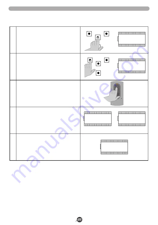
The learning of a transmitter can be activated through the “UP” button of the control unit or through the hidden button of a transmit-
ter already stored.
The control panel BIOS1 24V BOOMY always associates to the button of the transmitter the function STEP-BY-STEP.

1.

Make sure you are out of the programming menu.
To exit, briefly press the «MENU» button until you see the 
status of the control panel.

2.

Press and release the «UP» button. The sign 

rad

 appears 

on the display.

3.

Within 10 seconds, press the transmitter button to learn.

4.

If the storage was successful, the message 

don

 or 

fnd


appears on display, if the transmitter was already stored.

o

5.

After 2 seconds, the display shows the memory position 
where the remote control was stored (e.g., 

235

).

To store a new remote control, repeat the procedure from point 2.

WARNING!

 - After 10 seconds of inactivity the control panel exits the learning mode (the display shows 

tout

).











UP

DOWN

MENU

SS

UP

DOWN

MENU

SS

9.5 LEARNING OF TRANSMITTERS

Summary of Contents for 12007336

Page 1: ...7336 BOOMY 4 12007337 BOOMY 4 LED 12007337 BOOMY 4 LED 12007329 BOOMY 6 12007329 BOOMY 6 12007330 BOOMY 6 LED 12007330 BOOMY 6 LED Operatore irreversibile ambidestro per passi carrai 6 1622396 rev 3 2...

Page 2: ...HE PRELIMINARI e CARATTERISTICHE TECNICHE 6 5 INSTALLAZIONE ARMADIO e REGOLAZIONI 8 6 MOVIMENTAZIONE MANUALE DELL ASTA 16 7 COLLEGAMENTI ELETTRICI e PRIMO FUNZIONAMENTO 16 8 INSTALLAZIONE ACCESSORI 18...

Page 3: ...EN 12445 4 L installatore prima di installare il motore di movimentazione deve verificare che il cancello sia in buone condizioni meccaniche e che si apra e chiuda adeguatamente 5 L installatore dovr...

Page 4: ...per BOOMY 4 METRI n 2 spezzoni di alluminio di lunghezza 2 15 mt e 65 mm n 2 spezzoni di alluminio di lunghezza 2 15 mt e 65 mm Camicia di giunzione Camicia di giunzione n 2 tappi neri di copertura n...

Page 5: ...di motoriduttore con bilanciere e molle gi installate per aste di ARMADIO comprensivo di motoriduttore con bilanciere e molle gi installate per aste di 6 metri lamiera sagomata per fissaggio asta vit...

Page 6: ...messa a terra di sicurezza ATTENZIONE obbligatorio uniformare l impianto alle norme e alle leggi vigenti Descrizione 1 BOOMY 2 Fotocellule 3 Spire 4 Fotocellula in prossimit dell automazione PH3 5 Spi...

Page 7: ...issaggio asta CARATTERISTICHE TECNICHE U M BOOMY 4 BOOMY 4 LED BOOMY 6 BOOMY 6 LED Tensione alimentazione CT Vac 230 Frequenza di funzionamento CT Hz 50 Centrale di comando BIOS1 24 BOOMY Tensione ali...

Page 8: ...esistente e segnare dei punti in corrispondenza dei fori in cui verr fissato l armadio Fig 2 3 Spostare l armadio e praticare dei fori nei punti appena segnati 4 Inserire nei fori quattro ancoraggi ad...

Page 9: ...nare la piastra di fondazione a filo della superficie parallela all asta e perfettamente in bolla Fig 6 5 Attendere fino alla completa presa del calcestruzzo in genere almeno due settimane 6 Togliere...

Page 10: ...vra dell asta sia orientata a sinistra procedere effettuando le seguenti operazioni PER VERSIONE 4 METRI 1 Allentare il tirante e svitare la vite che lo blocca al bilanciere Fig 9 2 Rimuovere il tiran...

Page 11: ...Fig 15 4 Far passare i cavi di alimentazione dei led attraverso i fori appena fatti attraverso il passacavo dell armadio e attraverso il passacavo del box della centralina 5 Collegare le strisce led a...

Page 12: ...r passare i cavi attraverso il pas sacavo del box della centralina Fig 19 4 Collegare i cavi provenienti dal box alla schedina di interfaccia batterie Fig 20 ATTENZIONE Assicurarsi che la scheda non s...

Page 13: ...e successivamente rilasciare delicatamente l asta A seconda della posizione interna del motore potrebbe risultare che l asta si alzi leggermente quando rilasciata 6 Inserire per met la camicia di giun...

Page 14: ...a 45 Fig 27 8 Se non si riesce a regolare l asta in quanto la stessa tende a rimanere molto vicino alla posizione orizzontale procedere come segue sbloccare il motore portare la asta in posizione vert...

Page 15: ...Italiano 15 36 6 1622396 rev 3 21 09 2021 45 45 1 2 3 1 2 3 FIG 27 FIG 28...

Page 16: ...atamente il movimento naturale dell asta ATTENZIONE In caso di situazioni particolari in cui stato necessario muovere manualmente l asta una volta ripristinato il sistema consigliato effettuare nuovam...

Page 17: ...ostra LOP 3 Se l automazione NON MUOVE in apertura premere il tasto DOWN per fermare l apprendimento Il display mostra L 4 Premere il tasto SS per riprendere la procedura l automazione muove in apertu...

Page 18: ...ingressi PH3 e S3 vengono dedicati esclusivamente al sensore di presenza la fotocellula e la spira che sta in prossimit dell automazione e non possono essere adibiti ad altri tipi di intervento Come l...

Page 19: ...tto un ponticello tra il morsetto 9 e 10 8 3 INGRESSO COMANDO STOP 15 11 Collegare il comando STOP tra il terminale 11 e il comune 15 contatto NC Questo ingresso considerato una sicurezza l apertura d...

Page 20: ...alternano le migliaia senza puntini e le unit con puntini 9 PROGRAMMAZIONE CENTRALINA E FUNZIONALIT 9 1 DISPLAY DISPLAY DESCRIZIONE Standby automazione chiusa o accensione dopo spegnimento OP Automaz...

Page 21: ...ria power Viene visualizzato quando la tensione di alimentazione non sufficiente 9 3 SEGNALAZIONI DURANTE IL FUNZIONAMENTO LED COLORE DESCRIZIONE PH1 ROSSO Led normalmente acceso in caso di ingresso c...

Page 22: ...stato della centrale 2 Premere e rilasciare il tasto UP A display appare la scritta rad 3 Entro 10 secondi premere il tasto del trasmettitore da memorizzare 4 Se la memorizzazione avvenuta con success...

Page 23: ...uccesso a display appare la scritta CLr 5 Dopo 2 secondi il display mostra la posizione della memoria cancellata ATTENZIONE Dopo 10 secondi di inattivit la centrale esce dalla modalit apprendimento il...

Page 24: ...NU per almeno due secondi fino a quando il valore lampeggia Utilizzare i tasti UP o DOWN per modificare il valore Per salvare premere e mantenere premuto il tasto MENU per almeno due secondi Per uscir...

Page 25: ...il tempo tCL In questa fase il display mostra tC con il trattino lampeggiante che negli ultimi dieci secondi viene sostituito dal conto alla rovescia Un comando di apertura o l intervento delle fotoce...

Page 26: ...una pressione di SS comporta l arresto dell automazione Valore 2 alternato AP CH AP CH L utente non ha modo di fermare l automazione con il comando di SS Inviando il comando SS si ottiene l immediata...

Page 27: ...PH3 S3 0 0 5 3 IOM Modalit attivazione apertura IAO 0 0 su impegno 1 su disimpegno dopo impegno 0 0 1 4 ICM Modalit attivazione chiusura IAC 0 0 su impegno 1 su disimpegno dopo impegno 0 0 1 5 PH1 Po...

Page 28: ...3 intervento su finecorsa 1 0 3 14 SIt Tempo di intervento del sensore di corrente 2 1 10 x100ms 15 Sdt Tempo disabilitazione del sensore allo spunto 15 0 30 x100ms 16 ibM Azione da eseguire su rilev...

Page 29: ...ia e termina con la scritta don 32 SId Non in uso 1 SELEZIONE INGRESSO COMANDO APERTURA IAO 0 4 default 0 Con questo parametro si pu selezionare quale fotocellula o spira comanda l apertura ATTENZIONE...

Page 30: ...vimentazione 12 CONFIGURAZIONE LAMPEGGIO LED bLM 0 4 default 0 Selezione del tipo di lampeggio effettuato dai led su un tempo di ciclo di 500ms Valore 0 impulso normale 250ms ON 250ms OFF Valore 1 imp...

Page 31: ...i automatiche comprese le brevi o totali inversioni Tutte le sicurezze sono disabilitate tranne lo STOP 24 SOGLIA CICLI RICHIESTA PER ASSISTENZA Ser 0 100 x 1000 cicli default 0 possibile impostare da...

Page 32: ...tore Premere e mantenere premuto il tasto MENU finch il display stampa CLr rilasciare il tasto Per uscire dalla funzione premere brevemente il tasto MENU Se a display appare la scritta ERR ci sono pro...

Page 33: ...nzionamento andando a ripristinare tutte le funzionalit sopracitate che erano state disabilitate o modificate 24V TX fotocellule disabilitato Test fotocellule disabilitato Apertura chiusura da ingress...

Page 34: ...a err Errore memoria durante le funzioni visualizzazione posizione o cancellazione singolo trasmettitore 11 DICHIARAZIONE DI CONFORMIT Produttore Allmatic srl Indirizzo Via dell Artigiano 1 32026 Borg...

Page 35: ...4 GARANZIA La garanzia del produttore ha validit a termini di legge dalla data stampigliata sul prodotto ed limitata alla riparazione o sostitu zione gratuita dei pezzi riconosciuti dallo stesso come...

Page 36: ...ALLMATIC S r l 32026 Borgo Valbelluna Belluno Italy Via dell Artigiano n 1 Z A Tel 0437 751175 751163 r a Fax 0437 751065 www allmatic com E mail info allmatic com...

Page 37: ...007336 BOOMY 4 12007337 BOOMY 4 LED 12007337 BOOMY 4 LED 12007329 BOOMY 6 12007329 BOOMY 6 12007330 BOOMY 6 LED 12007330 BOOMY 6 LED Ambidextrous irreversible operator for driveways 6 1622396 rev 3 21...

Page 38: ...IONS AND TECHNICAL CHARACTERISTICS 6 5 CABINET INSTALLATION AND ADJUSTMENTS 8 6 MANUAL HANDLING OF THE BOOM 16 7 ELECTRICAL CONNECTIONS AND INITIAL OPERATION 16 8 INSTALLATION OF ACCESSORIES TO THE CO...

Page 39: ...453 EN 12445 4 Before installing the motion motor the installer must verify that the gate is in good mechanical conditions and that it adequately opens and closes 5 The installer must install the memb...

Page 40: ...inum length 2 15 meters and 65 mm No 2 pieces of aluminum length 2 15 meters and 65 mm Coupling for connection Coupling for connection No 2 black caps of cover No 2 black caps of cover 12007692 BOOM 6...

Page 41: ...INET including gear motor with rocker and springs already installed for 6 meter long CABINET including gear motor with rocker and springs already installed for 6 meter long boom boom fixing U shape pr...

Page 42: ...lant to the rules and laws in force Description 1 BOOMY 2 Photocells 3 Magnetic Loops 4 Photocell to detect presence near the automation PH3 5 Magnetic Loop to detect presence near the automation S3 6...

Page 43: ...pe profile TECHNICAL CHARACTERISTICS U M BOOMY 4 BOOMY 4 LED BOOMY 6 BOOMY 6 LED Control Unit power supply Vac 230 Frequency Hz 50 Control Unit BIOS1 24 BOOMY Motor power supply Vdc 24 Motor power con...

Page 44: ...et door Fig 1 2 Place the cabinet in the existing surface and mark points at the holes where the cabinet will be fixed Fig 2 3 Move the cabinet and drill holes in the points just marked 4 Insert four...

Page 45: ...grip place the foundation plate flush of the surface parallel to the boom and perfectly leveled Fig 6 5 Wait until the concrete is completely taken usually at least two weeks 6 Remove the four upper n...

Page 46: ...roceed by carrying out the following operations FOR THE 4 METERS VERSION 1 Loosen the tie rod and unscrew the screw that locks it to the rocker arm Fig 9 2 Remove the tie rod and the spring Fig 10 3 A...

Page 47: ...the bottom of the boom Fig 15 4 Pass the LED power cables through the holes just made through the cable hole of the cabinet and through the cable hole of the control box 5 Connect the led strips to th...

Page 48: ...t and pass the cables through the cable hole of the control box Fig 19 4 Connect the cables coming from the box to the card of battery interface Fig 20 WARNING Make sure the board is not powered befor...

Page 49: ...lease the boom gently Depending on the internal position of the motor the boom may rise slightly when released 6 Insert half of the coupling in the boom if necessary help yourself with a plastic head...

Page 50: ...f about 45 Fig 27 8 If you can not adjust the boom as the same tends to stay very close to the horizontal position proceed as follows unlock the motor bring the boom in vertical position lock the moto...

Page 51: ...English 15 36 6 1622396 rev 3 21 09 2021 45 45 1 2 3 1 2 3 FIG 27 FIG 28...

Page 52: ...natural movement of the boom ATTENTION In case of special situations where it was necessary to manually move the boom once the system is restored it is recommended to perform the learning procedure ag...

Page 53: ...LOP 3 If the automation DOESN T MOVE in opening press the DOWN button to stop the learning The display shows L 4 Press the SS button to restart the procedure the automation moves in opening at reduce...

Page 54: ...uts are exclusively dedicated to the presence sensor the photocell and the magnetic loop that is close to the automation and cannot be used for other types of intervention Like the STOP input PH3 and...

Page 55: ...idge must be made between terminal 9 and 10 8 3 STOP COMMAND INPUT 15 11 Connect the STOP control between terminal 11 and common 15 NC contact This input is considered a security the opening of the co...

Page 56: ...nds without dots and units with dots alternate 9 CONTROL UNIT PROGRAMMING AND FUNCTIONALITY 9 1 DISPLAY DISPLAY DESCRIPTION Standby closed automation or power ON after shutdown OP Automation is openin...

Page 57: ...isplay of the memory position power It is displayed when the supply voltage is not enought 9 3 ALERTS DURING OPERATION LED COLOUR DESCRIPTION PH1 RED Led normally on in case of input connected to an N...

Page 58: ...the status of the control panel 2 Press and release the UP button The sign rad appears on the display 3 Within 10 seconds press the transmitter button to learn 4 If the storage was successful the mess...

Page 59: ...2 seconds the display shows the location of the deleted memory WARNING After 10 seconds of inactivity the control panel exits the learning mode the display shows tout UP DOWN MENU SS UP DOWN MENU SS 9...

Page 60: ...MENU button for at least two seconds until the value flashes Use the UP or DOWN keys to change the value To save press and hold the MENU key for at least two seconds To exit without saving briefly pre...

Page 61: ...ng position the automation closes after waiting for the tCL time At this stage the display shows tc with the dash flashing which in the last ten seconds is replaced by the countdown An opening command...

Page 62: ...lore 2 alternated AP CH AP CH The user has no way to stop the automation with the command of SS By sending the command SS you get the immediate reversal of the gear 10 BEHAVIOUR AFTER BLACKOUT blt 0 2...

Page 63: ...n of the opening IAO 0 0 on commitment 1 on disengagement after commitment 0 0 1 4 ICM Mode of activation of the closing IAC 0 0 on commitment 1 on disengagement after commitment 0 0 1 5 PH1 Polarity...

Page 64: ...cle 3 intervention on mechanical stop 1 0 3 14 SIt Current sensor intervention time 2 1 10 x100ms 15 Sdt Current sensor override time at cue 15 0 30 x100ms 16 ibM Action to be performed on obstacle de...

Page 65: ...e 1 SELECT INPUT DEVICE FOR OPENING IAO 0 4 default 0 With this parameter you can select which photocell or loop controls the opening WARNING It is not possible to select PH3 or S3 for this function a...

Page 66: ...D during movement and OFF at the end of movement Value 4 FLASHING LED during movement and ON at the end of movement 12 CONFIGURATION OF LED FLASHING MODE bLM 0 4 default 0 Selection of the type of fla...

Page 67: ...and CLOSE The SS command is inactive All automatic operations including short or total reversals are disabled All security is disabled except the STOP 24 CYCLE THRESHOLD FOR ASSISTANCE REQUEST Ser 0...

Page 68: ...nsmitter s memory Press and hold the MENU button until the display prints CLr release the button To exit the function briefly press the MENU button If ERR appears on display there are problems with th...

Page 69: ...ctions that had been disabled or modified 24V TX photocells supply disabled Photocells functionality test disabled Opening closing from input devices IAO IAC disabled Led fixed on substitute with brie...

Page 70: ...emory err Memory error during position display functions or individual transmitter deletion 11 DECLARATION OF CONFORMITY Manufacturer Allmatic srl Address Via dell Artigiano 1 32026 Borgo Valbelluna B...

Page 71: ...t 13 PRODUCT DISPOSAL 14 WARRANTY The manufacturer s warranty is valid from the date stamped on the product and is limited to the repair or replacement free of charge of the parts recognized by the sa...

Page 72: ...ALLMATIC S r l 32026 Borgo Valbelluna Belluno Italy Via dell Artigiano n 1 Z A Tel 0437 751175 751163 r a Fax 0437 751065 www allmatic com E mail info allmatic com...

Page 73: ...7336 BOOMY 4 12007337 BOOMY 4 LED 12007337 BOOMY 4 LED 12007329 BOOMY 6 12007329 BOOMY 6 12007330 BOOMY 6 LED 12007330 BOOMY 6 LED Op rateur ambidextre irr versible pour voies d acc s 6 1622396 rev 3...

Page 74: ...S ET CARACT RISTIQUES TECHNIQUES 6 5 INSTALLATION ET R GLAGES DE L ARMOIRE 8 6 MANIPULATION MANUELLE DE LA LISSE 16 7 CONNEXIONS LECTRIQUES ET FONCTIONNEMENT INITIAL 16 8 INSTALLATION D ACCESSOIRES SU...

Page 75: ...L installateur avant d installer le moteur de mouvement doit v rifier que le portail de fer soit en bonnes conditions m caniques et qu il s ouvre et se ferme correctement 5 L installateur devra insta...

Page 76: ...m tres et 65 mm No 2 pi ces en aluminium de longueur 2 15 m tres et 65 mm Raccord pour la connexion Raccord pour la connexion No 2 couvercles noirs No 2 couvercles noirs 12007692 LISSE 6 M TRES LISSE...

Page 77: ...n moteur engrenages avec culbuteur et ressort d j install pour ARMOIRE comprenant un moteur engrenages avec culbuteur et ressort d j install pour une lisse de 6 m tres de long un profil de fixation en...

Page 78: ...obligatoire de se conformer aux r gles et lois en vigueur Description 1 BOOMY 2 Photocellule 3 Boucle magn tique 4 Cellule photo lectrique pour d tecter la pr sence pr s de l automatisation PH3 5 Bou...

Page 79: ...u profil en U CARACTERISTIQUES TECHNIQUES U M BOOMY 4 BOOMY 4 LED BOOMY 6 BOOMY 6 LED Alimentation de l unit de commande Vac 230 Frequence Hz 50 Unit de commande BIOS1 24 BOOMY Alimentation de moteur...

Page 80: ...acard Fig 1 2 Placer l armoire dans la surface existante et marquer les points aux trous o l armoire sera fix e Fig 2 3 D placer l armoire et percer des trous dans les points indiqu s 4 Ins rer quatre...

Page 81: ...de fondation au ras de la surface parall le la lisse et parfaitement nivel e Fig 6 5 Attendre que le b ton soit compl tement pris habituellement au moins deux semaines Fig 7 6 Retirer les quatre crous...

Page 82: ...oit orient e vers la gauche proc dez comme suit POUR LA VERSION 4 M TRES 1 Desserrer le tirant et d visser la vis qui la bloque sur le balancier Fig 9 2 Retirer le tirant et le ressort Fig 10 3 Fixer...

Page 83: ...ig 15 4 Faire passer les c bles d alimentation DEL travers les trous qui viennent d tre faits travers l orifice de c ble de l armoire et travers l orifice de c ble du bo tier de commande 5 Connectez l...

Page 84: ...ser les c bles par l orifice du c ble du bo tier de commande Fig 19 4 Connecter les c bles provenant du bo tier la carte de l interface de la batterie Fig 20 ATTENTION S assurer que la carte n est pas...

Page 85: ...eur avec la cl puis rel chez doucement la lisse Selon la position interne du moteur la lisse peut augmenter l g rement lorsqu elle est rel ch e 6 Ins rez la moiti de l accouplement dans la lisse si n...

Page 86: ...a lisse comme cela a tendance rester tr s proche de la position horizontale proc dez comme suit d verrouiller le moteur mettre la lisse en position verticale verrouiller le moteur d placer le tirant d...

Page 87: ...Fran ais 15 36 6 1622396 rev 3 21 09 2021 45 45 1 2 3 1 2 3 FIG 27 FIG 28...

Page 88: ...la lisse ATTENTION Dans des situations particuli res o il tait n cessaire de d placer manuellement la lisse une fois le syst me restaur il est recommand d effectuer nouveau la proc dure d apprentissa...

Page 89: ...ter l apprentissage L cran affiche L 4 Appuyer sur le bouton SS pour red marrer la proc dure l automatisation se d place en ouverture vitesse r duite jusqu ce qu elle atteigne l interrupteur de fin d...

Page 90: ...sont exclusivement d di es au capteur de pr sence la cellule photo lectrique et la boucle magn tique proche de l automatisation et ne peuvent pas tre utilis es pour d autres types d intervention Comme...

Page 91: ...t entre les bornes 9 et 10 8 3 ENTR E DE COMMANDE D ARR T D URGENCE 15 11 Connecter la commande STOP entre la borne 11 et la borne commune 15 contact NC Cette entr e est consid r e comme une s curit l...

Page 92: ...s alternent 9 PROGRAMMATION ET FONCTIONNALIT DE L UNIT DE COMMANDE 9 1 DISPLAY DISPLAY DESCRIPTION Veille automatisation ferm e ou mise sous tension apr s l arr t OP L automatisation s ouvre CL L auto...

Page 93: ...nsion d alimentation n est pas lev e 9 3 ALERTE LORS DU FONCTIONNEMENT LED COULEUR DESCRIPTION PH1 ROUGE Led normalement allum e en cas d entr e connect e un contact NC Signaler l activation de la cel...

Page 94: ...u de commande 2 Appuyez sur le bouton UP et rel chez le Le signe rad appara t l cran 3 Dans les 10 secondes appuyez sur le bouton de l metteur pour apprendre 4 Si le stockage a r ussi le message don o...

Page 95: ...bout de 2 secondes l affichage indique l emplacement de la m moire supprim e ATTENTION Apr s 10 secondes d inactivit le panneau de commande quitte le mode d apprentissage l cran affiche tout UP DOWN...

Page 96: ...moins deux secondes jusqu ce que la valeur clignote Utilisez les touches UP ou DOWN pour modifier la valeur Pour enregistrer appuyez sur la touche MENU et main tenez la enfonc e pendant au moins deux...

Page 97: ...i re dans la position d ouverture totale l automatisation se ferme apr s avoir attendu le temps tCL ce stade l affichage indique tc avec le tableau de bord clignotant qui dans les dix derni res second...

Page 98: ...sation pour arr ter Valeur 2 alternant AP CH AP CH L utilisateur n a aucun moyen d arr ter l automatisation avec la commande de SS En envoyant la commande de SS vous obtenez l inversion imm diate de l...

Page 99: ...1 4 S2 5 PH3 S3 0 0 5 3 IOM Mode d activation de l ouverture IAO 0 0 sur l engagement 1 sur d sengagement apr s engagement 0 0 1 4 ICM Mode d activation de la fermeture IAC 0 0 sur l engagement 1 sur...

Page 100: ...ntion sur but e m canique 1 0 3 14 SIt Temps d intervention du capteur de courant 2 1 10 x100ms 15 Sdt Le capteur de courant annule l heure au signal 15 0 30 x100ms 16 ibM Action effectuer sur la d te...

Page 101: ...URE IAO 0 4 default 0 Avec ce param tre vous pouvez s lectionner la cellule photo lectrique ou la boucle qui contr le l ouverture ATTENTION Il n est pas possible de s lectionner PH3 ou S3 pour cette f...

Page 102: ...vement et TEINTE la fin du mouvement Valeur 4 LED CLIGNOTANTE pendant le mouvement et ALLUM E la fin du mouvement 12 CONFIGURATION DU MODE CLIGNOTANT LED bLM 0 4 default 0 S lection du type de clignot...

Page 103: ...ion se d place exclusivement jusqu ce que le contr le soit pr sent la lib ration l automatisation s arr te Les commandes activ es sont OPEN et CLOSE La commande Pas Pas est inactive Toutes les op rati...

Page 104: ...ENU Maintenez enfonc e jusqu ce que l affichage affiche la valeur 0 rel chez le bouton S lectionnez l emplacement dans la m moire de l metteur Appuyez sur le bouton MENU et maintenez le enfonc jusqu c...

Page 105: ...nctions susmentionn es qui avaient t d sactiv es ou modifi es Alimentation des photocellules TX 24V d sactiv Photocellules test fonctionnel d sactiv Ouverture fermeture des p riph riques d entr e IAO...

Page 106: ...ur de m moire pendant les fonctions d affichage de position ou la suppression d un metteur individuel 11 D CLARATION DE CONFORMIT CE Fabricant Allmatic srl Adresse Via dell Artigiano 1 32026 Borgo Val...

Page 107: ...sive de ce produit 13 LIMINATION DU PRODUIT 14 GARANTIE La garantie du fabricant est valable partir de la date estampill e sur le produit et est limit e la r paration ou au remplacement sans frais des...

Page 108: ...ALLMATIC S r l 32026 Borgo Valbelluna Belluno Italy Via dell Artigiano n 1 Z A Tel 0437 751175 751163 r a Fax 0437 751065 www allmatic com E mail info allmatic com...

Page 109: ...36 BOOMY 4 12007337 BOOMY 4 LED 12007337 BOOMY 4 LED 12007329 BOOMY 6 12007329 BOOMY 6 12007330 BOOMY 6 LED 12007330 BOOMY 6 LED Operador irreversible ambidiestro para estacionamientos 6 1622396 rev 3...

Page 110: ...IONES PRELIMINARES Y CARACTER STICAS T CNICAS 6 5 INSTALACI N DE ARMARIO Y AJUSTES 8 6 MANIPULACI N MANUAL DE LA VARA 16 7 CONEXIONES EL CTRICAS Y PRIMER FUNCIONAMIENTO 16 8 INSTALACI N ACCESORIOS 18...

Page 111: ...instalador antes de instalar el motor de desplazamiento tiene que controlar que la cancela est en buenas condiciones mec nicas y que se abra y se cierre en forma adecuada 5 El instalador tendr que in...

Page 112: ...4 METROS por BOOMY VARA de 4 METROS por BOOMY n 2 trozos de aluminio de longitud 2 15 mt y 65 mm n 2 trozos de aluminio de longitud 2 15 mt y 65 mm Camisa de conexiones Camisa de conexiones n 2 tapas...

Page 113: ...tor con volante y muelle ya instalado para asta de 6 metros chapa Armario con motorreductor con volante y muelle ya instalado para asta de 6 metros chapa moldeada para fijaci n asta tornillos set de t...

Page 114: ...n conexi n a tierra de seguridad ATENCI N Es obligatorio uniformar la instalaci n a las normas y a las leyes vigentes Descripci n 1 BOOMY 2 Fotoc lulas 3 Espira 4 Fotoc lula cerca de la automatizaci n...

Page 115: ...la fijaci n CARACTER STICAS T CNICAS U M BOOMY 4 BOOMY 4 LED BOOMY 6 BOOMY 6 LED Tensi n de alimentaci n Vac 230 Frecuencia Hz 50 Central de mando BIOS1 24 BOOMY Tensi n de alimentaci n MOTOR Vdc 24 c...

Page 116: ...stente y marque puntos en los agujeros en los que se fijar el armario Fig 2 3 Mover el armario y perforar agujeros en los puntos reci n marcados 4 Insertar en los agujeros cuatro anclajes de expansi n...

Page 117: ...ar la placa de fijaci n al borde de la superficie paralela a la barra y perfectamente nivelado Fig 6 5 Espere hasta que la toma completa del hormig n por lo general al menos dos semanas Fig 7 6 Quitar...

Page 118: ...rientada a la izquierda procediendo de la siguiente manera PARA LA VERSI N 4 METROS 1 Afloje el tirante que lo sujeta al balanc n Fig 9 2 Quitar el tirante y la muelle de equilibrio Fig 10 3 Enganche...

Page 119: ...Fig 15 4 Hacer pasar los cables de alimentaci n de los led a trav s de los agujeros reci n hechos a trav s del pasacables del armario y a trav s del pasacables del box de la centralita 5 Conecte las t...

Page 120: ...armario y hacer pasar los cables a trav s del pasacables de la caja de la centralita Fig 19 4 Conecte los cables de la caja a la tarjeta de interfaz de bater as Fig 20 ATENCI N Aseg rese de que la tar...

Page 121: ...tinuaci n soltar suavemente la vara De pendiendo de la posici n interna del motor la vara puede levantarse ligeramente cuando se suelta 6 Insertar la mitad de la camisa de conexiones en la vara si es...

Page 122: ...Fig 27 8 Si no puede ajustar la vara ya que tiende a permanecer muy cerca de la posici n horizontal proceder como sigue desbloquear el motor colocar la vara en posici n vertical bloquear el motor desp...

Page 123: ...Espa ol 15 36 6 1622396 rev 3 21 09 2021 45 45 1 2 3 1 2 3 FIG 27 FIG 28...

Page 124: ...la vara ATENCI N En situaciones especiales en las que haya sido necesario mover la vara manualmente se recomienda que una vez restaurado el sistema se vuelva a realizar el procedimiento de aprendizaj...

Page 125: ...tura pulse la tecla DOWN para detener el aprendizaje La pantalla muestra L 4 Pulse la tecla SS para reanudar el procedimiento la automatizaci n se mueve en apertura a baja velocidad hasta que se alcan...

Page 126: ...e las entradas PH3 y S3 se dedican exclusivamente al sensor de presencia la fotoc lula y la espira que est cerca de la automatizaci n y no pueden utilizarse para otros tipos de intervenci n Como la en...

Page 127: ...se debe hacer un puente entre la abrazadera 9 y 10 8 3 ENTRADA DE CONTROL STOP 15 11 Conecte el mando STOP entre la terminal 11 y la comuna 15 contacto NC Esta entrada se considera una seguridad la a...

Page 128: ...es sin puntos y las unidades con puntos 9 PROGRAMACI N DE CENTRALITA Y FUNCIONALIDAD 9 1 DISPLAY DISPLAY DESCRIPCI N Standby automatizaci n cerrada o encendido despu s de apagado OP Automatizaci n se...

Page 129: ...9 3 SE ALES DURANTE EL FUNCIONAMIENTO LED COLOR DESCRIPCI N PH1 ROJO Led normalmente encendido en caso de entrada conectada a un contacto NC Reportar activaci n fotoc lula PH1 PH2 ROJO Led normalment...

Page 130: ...lse y suelte la tecla UP En pantalla aparece la inscripci n rad 3 En 10 segundos pulse la tecla del transmisor a almacenar 4 Si la memorizaci n ha tenido xito en pantalla aparece la inscripci n don o...

Page 131: ...ntalla aparece la inscripci n CLr 5 Despu s de 2 segundos la pantalla muestra la posici n de la memoria borrada ATENCI N Despu s de 10 segundos de inactividad la central sale del modo de aprendizaje l...

Page 132: ...ecla MEN duran te al menos dos segundos hasta que el valor parpadee Utilice las teclas UP o DOWN para cambiar el valor Para guardar pulse y mantenga pulsada la tecla MEN durante al menos dos segundos...

Page 133: ...despu s de esperar el tiempo tCL En esta fase la pantalla muestra tC con el gui n intermitente que en los ltimos diez segundos se sustituye por la cuenta atr s Un comando de apertura o la intervenci...

Page 134: ...na presi n de SS implica la parada de la automatizaci n Valor 2 alternado AP CH AP CH El usuario no tiene manera de detener la automatizaci n con el comando SS Enviando el comando SS se obtiene la inm...

Page 135: ...odo de activaci n de abrir IAO 0 0 por compromiso 1 por liberaci n tras el compromiso 0 0 1 4 ICM Modo de activaci n de cierre IAC 0 0 por compromiso 1 por liberaci n tras el compromiso 0 0 1 5 PH1 Po...

Page 136: ...3 intervenci n en fin de carrera 1 0 3 14 SIt Tiempo de intervenci n del sensor de corriente 2 1 10 x100ms 15 Sdt Tiempo de desactivaci n del sensor de arranque 15 0 30 x100ms 16 ibM Acci n a realizar...

Page 137: ...enta atr s y termina con la inscripci n don 32 SId No est en uso 1 SELECCI N DE ENTRADA DE CONTROL DE APERTURA IAO 0 4 default 0 Con este par metro se puede seleccionar qu fotoc lula o espira controla...

Page 138: ...ENDIDOS al final del movimiento Valor 3 Led INTERMITENTES durante el movimiento y APAGADOS al final del movimiento Valor 4 Led INTERMITENTES durante el movimiento y ENCENDIDOS al final del movimiento...

Page 139: ...a duraci n est definida por el par metro tpr 23 MODO HOMBRE PRESENTE dEA 0 1 default 0 En el modo HOMBRE PRESENTE la automatizaci n se mueve exclusivamente hasta que la orden est presente al soltar la...

Page 140: ...ecla MEN Mantenga pulsado hasta que la pantalla imprima el valor 0 suelte la tecla Seleccione la posici n en la memoria del transmisor Pulse y mantenga pulsada la tecla MEN hasta que la pantalla de pr...

Page 141: ...iento para restablecer todas las funciones antes mencionadas que hab an sido desactivadas o modificadas 24V TX fotoc lulas desactivado Pruebas fotoc lulas desactivado Apertura cierre por entradas IAO...

Page 142: ...err Error de memoria durante las funciones de visualizaci n de ubicaci n o eliminaci n de transmisor nico 11 DECLARACI N DE CONFORMIDAD Productor Allmatic srl Direcci n Via dell Artigiano 1 32026 Bor...

Page 143: ...TO 14 GARANT A La garant a del fabricante tiene validez en t rminos legales a partir de la fecha impresa y se limita a la reparaci n o sustituci n gratuita de las piezas reconocidas como defectuosas p...

Page 144: ...ALLMATIC S r l 32026 Borgo Valbelluna Belluno Italy Via dell Artigiano n 1 Z A Tel 0437 751175 751163 r a Fax 0437 751065 www allmatic com E mail info allmatic com...

Page 145: ...007336 BOOMY 4 12007337 BOOMY 4 LED 12007337 BOOMY 4 LED 12007329 BOOMY 6 12007329 BOOMY 6 12007330 BOOMY 6 LED 12007330 BOOMY 6 LED Voor zowel links als rechtshandige toepassingen 6 1622396 rev 3 21...

Page 146: ...N TECHNISCHE KENMERKEN 6 5 INSTALLATIE EN AFSTELLINGEN VAN DE BEHUIZING 8 6 HANDBEDIENING VAN DE BOOM MAST 16 7 ELEKTRISCHE AANSLUITINGEN EN EERSTE GEBRUIK 16 8 INSTALLATIE VAN ACCESSOIRES OP DE BESTU...

Page 147: ...e nstalleerd moet de installateur controleren of de slagboom in goede mechanische omstandigheden is en of deze goed opent en sluit 5 De installateur moet het onderdeel voor de handmatig ontkoppelen in...

Page 148: ...minium boom mast met per lengte 2 15 meter en 65 mm 2 15 meter en 65 mm Koppeling voor aansluiten Koppeling voor aansluiten Twee zwarte aflsuitdoppen Twee zwarte aflsuitdoppen 12007692 BOOM MAST VAN 6...

Page 149: ...ehuizing inclusief aandrijving met hefboombeugel en balansveer reeds ge nstalleerd voor Behuizing inclusief aandrijving met hefboombeugel en balansveer reeds ge nstalleerd voor 6 meter lange boom mast...

Page 150: ...aan de geldende regels en wetten Beschrijving 1 BOOMY 2 Fotocellen 3 Magnetische lussen 4 Fotocel om aanwezigheid in de buurt van de automatisering te detecteren PH3 5 Magnetische lus om aanwezigheid...

Page 151: ...ingsplaats K Het u vormige profiel wordt bevestigd TECHNICAL CHARACTERISTICS U M BOOMY 4 BOOMY 4 LED BOOMY 6 BOOMY 6 LED Voeding regeleenheid Vac 230 Frequentie Hz 50 Besturing BIOS1 24 BOOMY Motorvoe...

Page 152: ...1 2 Plaats de kast in het bestaande oppervlak en markeer de punten Bij de gaten waar de kast zal worden bevestigd Fig 2 3 Verplaats de kast en boor gaten in de gemarkeerde punten 4 Plaats vier draada...

Page 153: ...vlak op het oppervlak ligt parrallel aan de boom mast en perfect waterpas Fig 6 5 Wacht tot het beton volledig is uitgehard meestal minstens twee weken 6 Verwijder de vier bovenste moeren en sluitrin...

Page 154: ...rt u de volgende handelingen uit VOOR DE VERSIE VAN 4 METER 1 Maak de trekstang los en draai de inbusschroef los waarmee deze is vergrendeld op de balansstang Fig 9 2 Verwijder de trekstang en de veer...

Page 155: ...erkant van de boom mast bedekt Fig 15 4 Voer de LED voedingskabels door de zojuist gemaakte gaten door het kabelgat van de kast en door het kabelgat van de bedieningskast 5 Sluit de LED strips aan op...

Page 156: ...t en voer de kabels door de kabel gat in de bedieningskast Fig 19 4 Sluit de kabels die uit de doos komen aan op de kaart van de accu interface Fig 20 WAARSCHUWING Zorg ervoor dat de kaart niet van st...

Page 157: ...eutel en laat u de boom mast vervolgens voorzichtig los Afhankelijk van de interne positie van de motor kan de boom mast iets omhoog gaan wanneer hij wordt losgelaten 6 Steek de helft van de koppeling...

Page 158: ...neiging heeft om dicht bij de horizontale positie te blijven dan volgt u onderstaande stappen ontgrendel de motor breng de giek in verticale stand vergrendel de motor verplaats de trekstang zodanig d...

Page 159: ...Nederlandse 15 36 6 1622396 rev 3 21 09 2021 45 45 1 2 3 1 2 3 FIG 27 FIG 28...

Page 160: ...orzichtig de natuurlijke beweging van de boom LET OP In geval van speciale situaties waarin het noodzakelijk was de boom mast handmatig te verplaatsen wordt het aanbevolen om zodra het systeem is hers...

Page 161: ...de opening BEWEEGT drukt u op de knop OMLAAG om het leren te stoppen Het display toont L 4 Druk op de knop SS om de procedure opnieuw te starten De automatisering beweegt nu in opening met gereduceer...

Page 162: ...n zijn uitsluitend bestemd voor de aanwezigheidssensor de fotocel en de magnetische lus die dicht bij de automatisering ligt en kunnen niet worden gebruikt voor andere soorten interventies Net als de...

Page 163: ...moet er een kleine brug worden gemaakt tussen klem 9 en 10 8 3 INGANG STOPOPDRACHT 15 11 Sluit de STOPREGELING aan tussen klem 11 en common 15 NC contact Deze input wordt beschouwd als een beveiliging...

Page 164: ...n wisselen elkaar af 9 PROGRAMMERING EN FUNCTIONALITEIT VAN DE BESTURING 9 1 WEERGAVE WEERGAVE BESCHRIJVING Stand by gesloten automatisering of inschakelen na uitschakeling OP De automatisering opent...

Page 165: ...n de geheugenplaats verlaat vanwe ge inactiviteit power Deze wordt weergegeven wanneer de voedingsspanning niet voldoende is 9 3 WAARSCHUWINGEN TIJDENS BEDRIJF LED KLEUR BESCHRIJVING PH1 ROOD LED bran...

Page 166: ...eningspaneel ziet 2 Druk op de knop UP en laat deze weer los Het teken rad verschijnt op het display 3 Druk binnen 10 seconden op de knop van de afstandsbediening om te leren 4 Als het opslaan is gelu...

Page 167: ...ay 5 Na 2 seconden toont het display de locatie van de gewist geheugen WAARSCHUWING na 10 seconden inactiviteit verlaat de inbraakcentrale de leermodus op het display verschijnt Tout UP DOWN MENU SS U...

Page 168: ...de knop MENU totdat de waarde knippert Gebruik de toetsen UP of DOWN om de waarde te wijzigen Om op te slaan houdt u de toets MENU minstens twee seconden ingedrukt Druk kort op de toets MENU om af te...

Page 169: ...na het wachten op de TCL tijd Op dit moment toont het display tC met het knipperende streepje dat in de afgelopen tien seconden wordt vervangen door het aftellen Een openingsopdracht of photocell inte...

Page 170: ...CH De gebruiker heeft geen manier om de automatisering te stoppen met het commando van SS Door het commando SS te sturen krijg je de onmiddellijke omkering van de versnelling 10 GEDRAG NA STROOMSTORIN...

Page 171: ...de opening IAO 0 0 op verplichting 1 bij ontkoppeling na afspraak 0 0 1 4 ICM Activeringsmodus van het sluiten IAC 0 0 op verplichting 1 bij ontkoppeling na afspraak 0 0 1 5 PH1 Polariteit PH1 ingang...

Page 172: ...ep bij mechanische aanslag 1 0 3 14 SIt Huidige interventietijd van de sensor 2 1 10 x100ms 15 Sdt Tijd voor het opheffen van de huidige sensor bij het signaal 15 0 30 x100ms 16 ibM Actie die moet wor...

Page 173: ...1 SELECTEER INVOERAPPARAAT VOOR HET OPENEN VAN DE IAO 0 4 standaard 0 Met deze parameter kunt u selecteren welke fotocel of lus de opening bestuurt WAARSCHUWING Het is niet mogelijk om PH3 of S3 te s...

Page 174: ...einde van beweging Waarde 4 KNIPPERENDE LED tijdens beweging en AAN het einde van beweging 12 CONFIGURATIE VAN LED KNIPPERMODUS BLM 0 4 standaard 0 Selectie van het type flitsen dat door de LED s wor...

Page 175: ...h uitsluitend tot de besturing aanwezig is bij het vrijkomen stopt de automatisering De ingeschakelde opdrachten zijn GEOPEND en GESLOTEN De SS opdracht is inactief Alle automatische bewerkingen inclu...

Page 176: ...te drukken Houd ingedrukt totdat de waarde 0 op het display wordt afgedrukt en laat de knop los Selecteer de locatie in het geheugen van de zender Houd de knop menu ingedrukt totdat CLR op het displa...

Page 177: ...functies te herstellen die waren uitgeschakeld of gewijzigd 24V TX fotocellen leveren uitgezet Functietest fotocellen uitgezet Openen sluiten van invoerapparaten IAO IAC uitgezet LED vast aan vervang...

Page 178: ...heugenfout tijdens functies voor positieweergave of het verwijderen van afzonderlijke zenders 11 CONFORMITEITSVERKLARING Fabrikant Allmatic srl Adres Via dell Artigiano 1 32026 Borgo Valbelluna BL Ita...

Page 179: ...rantie van de fabrikant is geldig vanaf de datum die op het product is gestempeld en is beperkt tot de gratis reparatie of vervan ging van de onderdelen die door dezelfde als defect zijn erkend als ge...

Page 180: ...ALLMATIC S r l 32026 Borgo Valbelluna Belluno Italy Via dell Artigiano n 1 Z A Tel 0437 751175 751163 r a Fax 0437 751065 www allmatic com E mail info allmatic com...

Reviews: