


Français - 11 / 36
6-1622396 - rev. 3 - 21/09/2021
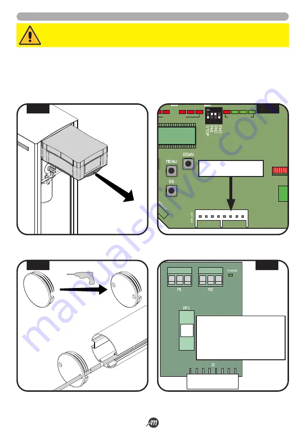
5.3 INSTALLATION AVEC KIT LED (EN OPTION) - UNIQUEMENT POUR LA VERSION 4 MÈTRES
1.
Sortir le boîtier de l’unité de commande et retirer le couvercle en dévissant les vis (Fig.13).
2.
Installer la carte d’interface LED dans l’emplacement approprié (dans la version BOOMY 4 LED, la carte est déjà installée)
(Fig.14).
3.
Percer deux trous de 6 mm Ø sur le capuchon en plastique noir qui recouvre le bas de la lisse (Fig.15).
4.
Faire passer les câbles d’alimentation à DEL à travers les trous qui viennent d’être faits, à travers l’orifice de câble de l’armoire
et à travers l’orifice de câble du boîtier de commande.
5.
Connectez les bandes de LED à la carte de LED (Fig.16).
ATTENTION!
S’assurer que la carte n’est pas sous tension avant d’effectuer les connexions.
G
R +24
G
R +24
Description:
G
Canal VERT de LED
R
Canal ROUGE de LED
+24
Alimentation de LED +24Vdc
PF1
Fusible T 1A
J1
Connecteur enfichable
1
LED RADIO
FUSE 1
FUSE 2
J2
J1
J3
2
3
4
5
6
7
8
9 10
11 12 13 14 15 16 17
20 21
LED STATUS
LED STATUS
J4
FENTE POUR LA CARTE
D’INTERFACE LED
2 x Ø 6mm
FIG. 13
FIG. 14
FIG. 15
FIG. 16
Summary of Contents for 12007336
Page 15: ...Italiano 15 36 6 1622396 rev 3 21 09 2021 45 45 1 2 3 1 2 3 FIG 27 FIG 28...
Page 51: ...English 15 36 6 1622396 rev 3 21 09 2021 45 45 1 2 3 1 2 3 FIG 27 FIG 28...
Page 87: ...Fran ais 15 36 6 1622396 rev 3 21 09 2021 45 45 1 2 3 1 2 3 FIG 27 FIG 28...
Page 123: ...Espa ol 15 36 6 1622396 rev 3 21 09 2021 45 45 1 2 3 1 2 3 FIG 27 FIG 28...
Page 159: ...Nederlandse 15 36 6 1622396 rev 3 21 09 2021 45 45 1 2 3 1 2 3 FIG 27 FIG 28...


