12
ENGLISH
INDEX
IMPORTANT REMARKS 12
MODELS AND FEATURES
13
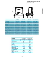
TECHNICAL DATA 13
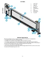
SET PANEL 14
PREVIOUS INSPECTIONS 14
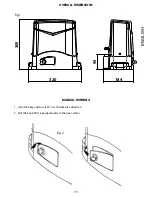
OVERALL DIMENSIONS 15
MANUAL RUNNING 15
INSTALLATION 16
FIXING 17
RACK ASSEMBLING 18
LIMIT SWITCH FIXING 19
MAINTENANCE
20
DISPOSAL
20
INDEX
IMPORTANT REMARKS
For any installation problems please contact
Allmatic S.r.l. TEL. (+39) 0437 751175
has the right to modify the product without previous notice; it also declines any responsibility to damage or injury to
people or things caused by improper use or wrong installation.
Please read this instruction manual very carefully before installing and programming your control unit.
• This instruction manual is only for qualified technicians, who specialize in installations and automations.
• The contents of this instruction manual do not concern the end user.
• Every programming and/or every maintenance service should be done only by qualified technicians.
AUTOMATION MUST BE IMPLEMENTED IN COMPLIANCE WITH THE EUROPEAN REGULATIONS IN FORCE:
EN 60204-1
(Machinery safety. electrical equipment of machines, part 1: general rules)
EN 12445
(Safe use of automated locking devices, test methods)
EN 12453
(Safe use of automated locking devices, requirements)
• The installer must provide for a device (es. magnetotermical switch) ensuring the omnipolar sectioning of the
equipment from the power supply.
The standards require a separation of the contacts of at least 3 mm in each pole (EN 60335-1).
• The plastic case has an IP55 insulation; to connect flexible or rigid pipes, use pipefittings having the same insulation
level.
• Installation requires mechanical and electrical skills, therefore it shall be carried out by qualified personnel only, who
can issue the Compliance Certificate concerning the whole installation (Machine Directive 2006/42/CEE, Annex IIA).
• The automated vehicular gates shall comply with the following rules: EN 13241-1, EN 12453, EN 12445 as well as any
local rule in force.
• Also the automation upstream electric system shall comply with the laws and rules in force and be car-
ried out workmanlike.
• The door thrust force adjustment shall be measured by means of a proper tool and adjusted according to
the max. limits, which EN 12453 allows.
• We recommend to make use of an emergency button, to be installed by the automation (connected to
the control unit STOP input) so that the gate may be immediately stopped
in case of danger.
• The appliance is not to be used by children or persons with reduced physical, sensory or mental capabili-
ties, or lack of experience and knowledge, unless they have been given supervision or instruction.
• Children being supervised do not play with the appliance.


