background image

17

ENGLISH

FIXING

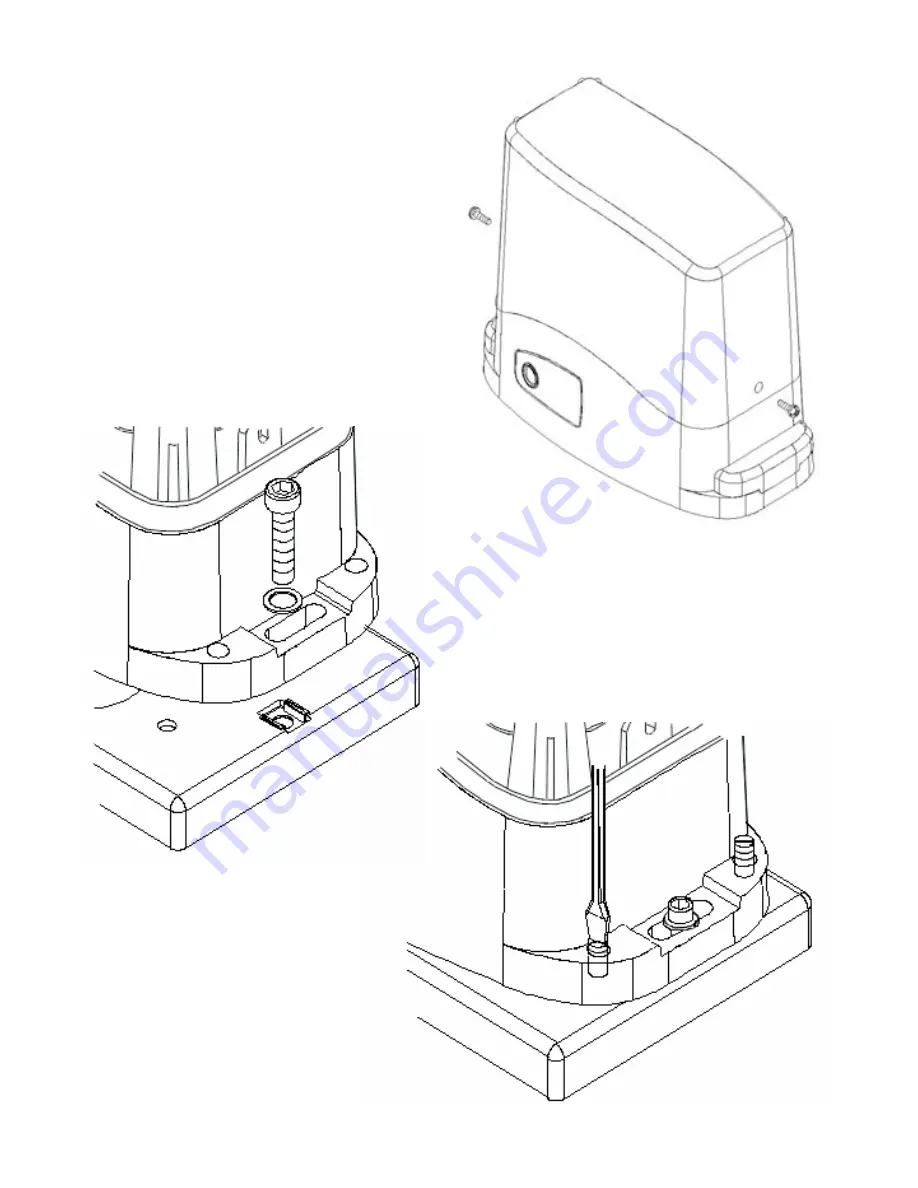
Take the lid off unscrewing the

screws (fig.5).

Put the gear-motor on the plate. 

Insert the two socket head screws (fig.6).

fig.5

fig.6

fig.7

It is important to lock the two socket head 

screws forcefully, making sure, that the gear-

motor is steady on the ground, during the whole 

gate running.

If the regulating allowed by the 

rack is not sufficient, it is possible to 

counterbalance the gear-motor high 

working on the four screws (fig.7).

Summary of Contents for KALOS 110 24V

Page 1: ...KALOS 50 KALOS 80 KALOS 120 KALOS 80 120 Vac KALOS 70 24V KALOS 110 24V Made in Italy Gear motor for sliding gates GB INSTRUCTION MANUAL...

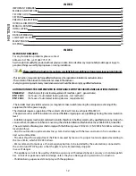
Page 2: ...provideforadevice es magnetotermicalswitch ensuringtheomnipolarsectioningofthe equipmentfromthepowersupply Thestandardsrequireaseparationofthecontactsofatleast3mmineachpole EN60335 1 Theplasticcasehas...

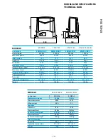
Page 3: ...m s 0 19 m s Maximum thrust 400 N 650 N 1000 N 650 N Gate maximum weight 500 Kg 800 Kg 1200 Kg 800 Kg Thermoprotection 150 C 150 C 150 C 160 C Duty cicle 30 30 30 30 Operation temperature 20 55 C 20...

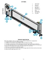
Page 4: ...unning 3_ The system of wheels lower rail and roller upper runner must work without too many frictions 4_ To avoid the gate derailment you must install the stop beats of the sliding whether at the ope...

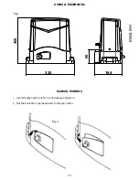
Page 5: ...320 184 95 305 15 ENGLISH OVERALL DIMENSIONS MANUAL RUNNING 1_ Insert the key and turn it 90 in anticlockwise direction 2_ Pull the knob till it is perpendicular to the gear motor fig 1 fig 2...

Page 6: ...base plate through 4 sturdy screw anchors fig n 3 or drown it into the concrete fig n 4 Plan for one or more sheathing for the passage of the power lines NB It is necessary to know the rack dimension...

Page 7: ...screws fig 6 fig 5 fig 6 fig 7 It is important to lock the two socket head screws forcefully making sure that the gear motor is steady on the ground during the whole gate running If the regulating al...

Page 8: ...y bringing the pinion gear into line with the last spacing bar Fasten the rack element for good For a correct positioning of the other elements and to assure their straightness it is necessary to empl...

Page 9: ...t the limit switch brackets don t collide with the pinion gear Haul the gate manually at the opening leaving depending on the gate weight a crack from 30 to 50 mm between the main gate and mechanical...

Page 10: ...label that instructs to keep children away from the moving door or place the appropriate symbol ISO 3864 see symbol FINAL RECOMMENDATIONS Keep the remote control out of the reach of children and do no...

Page 11: ...d mail to Allmatic S r l Via dell Artigiano 32020 Lentiai BL Allmatic ensures that its products are flawless and that they underwent quality and functionality tests Allmatic technical service will dec...

Page 12: ...Made in Italy 6 1624806 rev 1 09 07 2013 ALLMATIC S r l 32020 Lentiai Belluno Italy Via dell Artigiano n 1 Z A Tel 0437 751175 751163 r a Fax 0437 751065 http www allmatic com E mail info allmatic com...

Reviews: