22
2.2.8
Application (Compact Fixed Dome Excluded)
The Application setting can be found under this path:
System> Application
.
The IP Camera equips one alarm i nput and one relay output for cooperating
with alarm system to catch events’ images. Refer to alarm pin definition below to
connect alarm devices to the IP Camera if needed.
Alarm Pin Definition
Please refer to
User
’s Manual
for Alarm Pin Definition to connect the alarm
devices.
Alarm Switch
The Administrator can enable or disable the alarm function.
Alarm Type
Select an alarm type, <Normal close> or <Normal open>, that corresponds with
the alarm application.
Alarm Output
Define alarm output signal <high> or <low> as the normal alarm output status
according to the current alarm application.
Triggered Action (Multi-option)
The Administrator can specify alarm actions that will take when the alarm is
triggered. All options are listed as follows:
Enable Alarm Output
Select the item to enable alarm relay output.
IR Cut Filter
Select the item and the camera’s IR cut filter (ICR) will be removed (on)
or blocked (off) when alarm input is triggered.
Note:
The IR Function (Refer to
IR Function
) could not be set as
<Auto> mode if this triggered action is enabled.
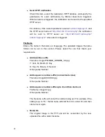
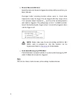
Send Message by FTP/E-Mail
The Administrator can select whether to send an alarm message by FTP
and/or E-Mail when an alarm is triggered.

