background image


Mute the volume using the button labeled “MUTE”. To raise the volume again after muting, 

press the Mute button to take the volume level to where it was prior to muting. In Mute mode, 

the light above the “operate” button on the front panel of the L-9000 OTL/OCL will not be 

illuminated; it will illuminate when the L-9000 OTL/OCL is unmuted again. 


Use the red power on/off button in the top left-hand corner of the remote control to power the 

L-9000 OTL/OCL on and off. 


INITIAL POWER-ON 


Once you have your L-9000 OTL/OCL in place and all connections have been made to your sources 

and amplifier(s) and the power cord is installed and plugged into an AC receptacle, you are ready to 

turn on the power for your L-9000 OTL/OCL. Before you power up the L-9000 OTL/OCL, though, be 

sure you have: 


CAREFULLY AND SLOWLY removed ALL the cardboard cushion materials from inside the tube 

chimneys


ensured all tubes are snugly in their sockets


ensured the batteries are in the remote control – if not, insert the batteries (by removing 

plate on the bottom of the remote control)


turned the volume down on, or muted the L-9000 OTL/OCL  


checked that all your connections are snug 


Also,  be  sure  you  have  manually  turned  the  volume  control  on  the  front  panel  to  the  extreme 

counter-clockwise position (minimum volume). 


Push the power on-off switch to the left of the IEC connector (facing the left side of the unit as in 

Figure 1) so it is in the “on position”. That will power up the L-9000 OTL/OCL. From this point on, 

you need only use the far left hand button marked “power” on the front panel or the power button 

on the remote control to turn the L-9000 OTL/OCL on and off. 


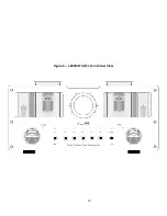
Once the power has been turned on, the following will happen on the front panel (Please see Figure 

4): 


the light above the “power” button will illuminate 


the meters on the front panel will illuminate 


the light over the line source button that is depressed will illuminate 


after about 40 seconds, the light over the “operate” button will illuminate. The L-9000 OTL/OCL 

has a “soft start” delay for the tubes in order to extend tube life. 


FINAL/3

rd

 GAIN STAGE BALANCING USING THE CURRENT METERS 


There is one current meter for each channel on the front of the L-9000 (See Figure 4). These meters 

indicate the potential for DC from the output of the third gain stage tubes in the L-9000 OTL/OCL, 

the 6080s. 

Summary of Contents for L-9000

Page 1: ...ALLNIC AUDIO L 9000 OTL OCL LINE STAGE PREAMPLIFIER OWNER S MANUAL...

Page 2: ...sound of this high quality device will be rewarded by its excellent operation for years to come Please read this entire manual before you connect the L 9000 OTL OCL Line Stage Preamplifier to the oth...

Page 3: ...tion Location Power Connection Inputs Outputs Remote Control 7 8 8 8 8 INITIAL POWER ON 9 OPERATION 10 CURRENT METERS 11 TUBES 11 SPECIFICATIONS 12 WARRANTY 13 FIGURES 14 Please read about SAFETY befo...

Page 4: ...detailed expression natural harmonics and subtle musical decay The lowest possible distortion The widest musical dynamics In the L 9000 there is no coupling device between the preamplifier and the pow...

Page 5: ...its kind for Allnic Audio The L 9000 OTL OCL does not employ a digital IC volume control or a low cost carbon film volume control with a motor The L 9000 OTL OCL uses the WORLD S FIRST 61 step consta...

Page 6: ...stically with the L 9000 OTL OCL in your system 3 Be sure the L 9000 OTL OCL is labeled for the AC voltage of your location If it is not DO NOT connect it to your AC outlet Please contact your Allnic...

Page 7: ...nit is not a good thing DO NOT place the unit near a strong light or heat source DO NOT place anything heavy on the unit DO NOT allow rubber or vinyl materials to rest on the unit s chassis for long p...

Page 8: ...ppropriate types of connections or adaptors The L 9000 OTL OCL has been designed and manufactured to work most synergistically with Allnic Audio phono preamplifiers pre preamplifiers equalization and...

Page 9: ...e volume down on or muted the L 9000 OTL OCL checked that all your connections are snug Also be sure you have manually turned the volume control on the front panel to the extreme counter clockwise pos...

Page 10: ...e some time to get an approximate balance but once set it should rarely if ever move The Allnic Audio L 9000 OTL OCL is now ready for operation At this point you can power on your sources and finally...

Page 11: ...owing the drop for the one in the other channel If that still does not rectify the situation one or both of the 6080 tubes may need to be replaced Within the tube warranty period if any 6080 tube is o...

Page 12: ...Voltage Gain 18dB THD 1kHz Less than 0 03 1kHz 1V RMS S N Ratio 100dB CCIR 1kHz Maximum Output 20V RMS Non clipping Output Impedance 90 Power Consumption 120W at 110 120V 60 Hz 120W at 220 230V 50 Hz...

Page 13: ...anufacturing defects for one 1 year from date of purchase The warranty is transferable for the balance of the original purchaser s warranty period provided as stated below no unauthorized repairs or m...

Page 14: ...14 FIGURES Figure 1 L 9000 OTL OCL Left Side Panel View...

Page 15: ...15 Figure 2 L 9000 OTL OCL Rear Panel View Figure 3 L 9000 OTL OCL Remote Control...

Page 16: ...16 Figure 4 L 9000 OTL OCL Front Panel View...

Page 17: ...17 Figure 5 L 9000 OTL OCL Top View...

Reviews: