background image


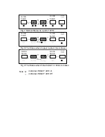
Note : 

  indicates LNK/ACT LED Lit 


indicates LNK/ACT LED Off 


 ● ○


 ○ ○ 


 ○


  C 

10/100 
Switch 

10/100 
Switch 

Fibre Cable  

 A 

  TP


TP

LFP 

LFP 


Fibre Cable  

  B 

 A 


○ ○


  C 

○ ○


 TP


    TP

10/100 
Switch 

Remote 

Station 

 10/100 
 Switch 

LFP 

LFP 

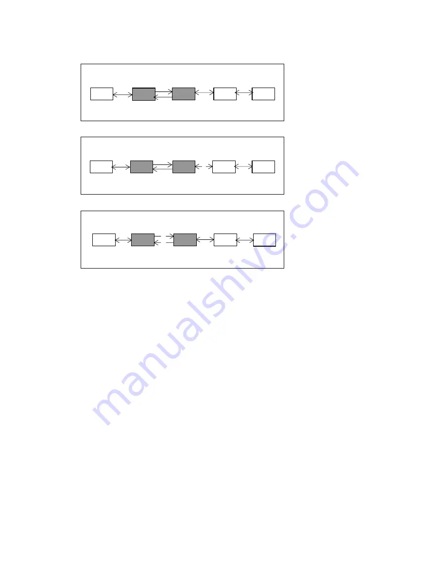
Fig. 7 Normal Status via a pair of LFP’s 


   A 

10/100 
Switch 

LFP 


LFP 

  10/100 
  Switch 

TP


TP

Fibre Cable  

  C 

● ●


Remote 

Station 

● ●


Fig. 8 The Status when Copper Cable A link is broken 

Remote 

Station 

Fig. 9 The Status when Fibre Cable C or B link is broken 

Summary of Contents for 10/100 Base-TX to 100Base-FX Converter POE Power Provider POE100 Series

Page 1: ...POE100 Series 10 100 Base TX to 100Base FX Converter POE Power Provider Version 1 01 Date 13 July 2005...

Page 2: ...E 802 3af standard The converters include PD Power Devices POE120 Series IP Phones Wireless Access Points etc signature sensing and power monitoring features compliant with the IEEE 802 3af standard T...

Page 3: ...ect the copper cable to your IEEE 802 3af compliant PD device e g Wireless Access Point IP Phone IP Camera Note The POE100 can also work as a standard media converter and connect to a non POE device 3...

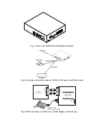
Page 4: ...Converter Fig 2 Example connection between POE100 PD device and Fibre Cable Fig 3 POE100 Series to PD Device or POE Splitter VOIP Phone RX TX TX RX VOIP PoE Phone PoE PD or PoE Splitter POE100 Series...

Page 5: ...POE100 Series Media Converter Front Panel Fig 5 POE100 Series Media Converter Rear Panel Fig 6 Pairs used for transmitting power over Ethernet Cable Note The pins used for delivering power to the Powe...

Page 6: ...s unplugged the converter stops transmission on the fibre port This causes the remote fibre node link to fail as well The LED s on the converter will now show link failure on both the copper and fibre...

Page 7: ...P Fibre Cable B A C TP TP 10 100 Switch Remote Station 10 100 Switch LFP LFP Fig 7 Normal Status via a pair of LFP s A B 10 100 Switch LFP LFP 10 100 Switch TP TP Fibre Cable C Remote Station Fig 8 Th...

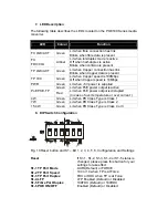
Page 8: ...PoE power output is active PoE PSE TP Red Lit when PoE power output is disrupted In case of over temperature or over current 4W Green Lit when PD Class Type is Class 1 7W Green Lit when PD Class Type...

Page 9: ...alf Duplex 412m Multi Mode Full Duplex 2Km Single Mode Half Duplex 412m Single Mode Half Duplex 5 20 40 60 80 100Km 10 Technical Specifications Standards IEEE 802 3u 10 100Base TX 100Base FX IEEE 802...

Reviews: