background image

GSS Series User Manual 


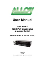
User Manual 


GSS Series 

16/24 Port Gigabit Web 

Managed Switch 


(GSS-16T4SFP & GSS-24T4SFP) 


Version 1.0 

Sep. 2007 

Alloy Computer Products Pty Ltd Copyright ©2007 

1


Summary of Contents for GSS-16T4SFP

Page 1: ...GSS Series User Manual User Manual GSS Series 16 24 Port Gigabit Web Managed Switch GSS 16T4SFP GSS 24T4SFP Version 1 0 Sep 2007 Alloy Computer Products Pty Ltd Copyright 2007 1...

Page 2: ...or 1000SX LX ZX SFP Modules 12 3 OPERATION OF THE WEB BASED MANAGEMENT 14 3 1 WEB MANAGEMENT HOME OVERVIEW 15 3 2 CONFIGURATION 16 3 2 1 System Information 16 3 2 2 Ports 18 3 2 3 VLAN Mode 20 3 2 4 V...

Page 3: ...A computing device pursuant to Subpart J of Part 15 of FCC Rules which are designed to provide reasonable protection against such interference when operated in a commercial environment European Commu...

Page 4: ...FP differ in terms of port density the former model offering 16x 10 100 1000Mbps Gigabit Ethernet ports and the latter 24x ports of the same specification In all other respects web management interfac...

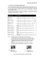
Page 5: ...m max range 40Km 1000Mbps single mode 1000Base ZX 1550nm max range 70Km 1000Mbps single mode 1000Base EZX 1550nm max range 120Km 1000Mbps WDM single mode single core 1310nm max range 20Km 1000Mbps WDM...

Page 6: ...ilover function Port mirroring function 1 3 Checklist Before you start installing your switch verify that the package contains the following A GSS 16T4SFP or GSS 24T4SFP Gigabit Web Managed Switch Mou...

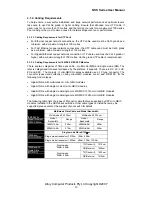
Page 7: ...hernet ports 4x SFP fibre ports and 1x reset button to restore factory configuration Gigabit Ethernet Ports LED Display Panel Factory Default Button SFP Fibre Ports Fig 1 3 Front Panel of the GSS 16T4...

Page 8: ...000Mb link Lit amber when 100Mb link Off when 10Mb link or no link present Gigabit Fibre Ports SFP LINK ACT Green Lit when link is active flashes when traffic present Note All SFP ports are paired wit...

Page 9: ...e 70Km MGBIC SLC120 1000Mbps single mode 1000Base EZX 1550nm max range 120Km MGBIC WDMS3 20 1000Mbps WDM single mode single fibre 1310nm max range 20Km MGBIC WDMS5 20 1000Mbps WDM single mode single f...

Page 10: ...g or unplug them while the power is applied to the switch 1 Verify that the mini GBIC module is compatible with the SFP port on the switch for example some switch manufacturers design their mini GBIC...

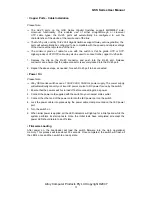
Page 11: ...the above steps as needed for each RJ 45 port to be connected Power On Please Note Alloy GSS series switches use a 100 240 VAC 50 60 Hz power supply The power supply will automatically convert your l...

Page 12: ...s These are SX LX LHX ZX and EZX The majority of mini GBIC modules available use a LC type connector The connector types used currently on Alloy mini GBIC modules are LC and WDM SC for the following m...

Page 13: ...ll figures denoting the range a given cable type can achieve must be treated as maximum values A number of variables can limit the actual range that can be achieved grade of cable used quality of cabl...

Page 14: ...To access the web management open a web browser such as Internet Explorer or Mozilla Firefox and enter the default IP address into the address bar The default network settings for the GSS Series are s...

Page 15: ...configure port trunk groups LACP Used to configure LACP Link Aggregation Control Protocol settings 802 1x Used to configure 802 1x authentication settings IGMP Snooping Used to configure IGMP setting...

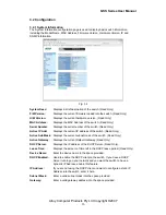
Page 16: ...the switch Read Only Active Sub Mask Displays the current subnet mask of the switch Read Only Active Gateway Displays the current Default Gateway Read Only DHCP Server Displays the IP address of the D...

Page 17: ...word of the switch please enter it here Default password is admin Inactivity Timeout Used to automatically log you out of the management interface after a specified inactivity time Time is measured in...

Page 18: ...Link Status Description 1000FDX Port is running at 1000M Full Duplex 100FDX Port is running at 100M Full Duplex 100HDX Port is running at 100M Half Duplex 10FDX Port is running at 10M Full Duplex 10H...

Page 19: ...lex equipment tick the check box to enable this feature Apply Button The Apply button must be pressed after making any changes to any of the values on this screen Refresh Button Used to refresh the cu...

Page 20: ...d be used in an internet caf where all computers are not allowed to communicate with each other but must communicate to a single port for internet access The switch would then be configured with 7 vla...

Page 21: ...t Double Tag Double Tag also known as Q in Q is used to encapsulate a second VLAN tag inside an Ethernet packet This type of scenario is mainly used for service provider networks The inner VLAN tag is...

Page 22: ...ill appear as shown below Fig 3 6 Description Enter a Descriptive name for the VLAN Ports Select what ports you want to be members of this VLAN and tick there corresponding check boxes Select All Used...

Page 23: ...ged and untagged packets or only allow each port to accept Tagged packets Tag Out Enabled Tick this check box to enable all packets being sent from this port to be tagged If you are enabling this feat...

Page 24: ...next to the VLAN you wish to modify and click modify Delete Select the radio button next to the VLAN you wish to delete and click delete Refresh Button Used to refresh the current settings displayed o...

Page 25: ...r as shown below Fig 3 10 Description Enter a Descriptive name for the VLAN Ports Select what ports you want to be members of this VLAN and tick there corresponding check boxes Select All Used to auto...

Page 26: ...n this screen Fig 3 11 Modify Select the radio button next to the VLAN you wish to modify and click modify Delete Select the radio button next to the VLAN you wish to delete and click delete Refresh B...

Page 27: ...e Apply button must be pressed after making any changes to any of the values on this screen Fig 3 12 Modify Select the radio button next to the VLAN you wish to modify and click modify Delete Select t...

Page 28: ...aggregate multiple ports together to form a high bandwidth backbone link Fig 3 13 Group Port Is the built in trunking groups allowed to be configured The switch supports a maximum of 8 Trunk groups 1...

Page 29: ...lue Fig 3 14 Port The physical ports of the switch Protocol Enabled Tick the checkbox to enable LACP on the particular port Apply Button The Apply button must be pressed after making any changes to an...

Page 30: ...riority Is a value used to identify the root bridge of the spanning tree network The bridge with the lowest values has the highest priority and becomes the root 16 Values are allowed by the switch ran...

Page 31: ...ue set to each port to allow the switch to determine which port will be a forwarding port The lowest path cost value will be used as the forwarding port Enter a value between 1 and 20000000 or it can...

Page 32: ...he authentication server to authenticate and verify the username and password and the server then tells the authenticator if the request has been granted access for that port Fig 3 15 Mode Used to ena...

Page 33: ...RADIUS server Force Re initialise forces the port to re initialise with the RADIUS server Statistics displays the 802 1x statistics of each individual port Fig 3 16 Refresh Button Used to refresh the...

Page 34: ...before re authentication occurs Time interval can be set between 1 and 3600 seconds EAP Timeout Used to set the timeout value of the EAP authentication Time interval can be set between 1 and 255 secon...

Page 35: ...packets forwarded to a multicast address will be forwarded to all members belonging to the multicast group Fig 3 19 IGMP Enabled Used to enable or disable the IGMP function Router Ports Used to speci...

Page 36: ...port and several other ports being monitored by the one port Fig 3 20 Mirror Port Select the port you would like to use as the capturing port This port will be plugged directly to a PC running Packet...

Page 37: ...iorities can be set based on the value of the TOS filed bits 3 2 11 1 Quality of Service 802 1p Fig 3 21 QoS Mode Used to set the required QoS method Options are 802 1p and DSCP Prioritise Traffic Use...

Page 38: ...lue 0 63 Used to apply a particular priority class to a certain DSCP value Only 7 DSCP Values can have a priority class assigned to it All other DSCP values will be assigned the same priority class Pr...

Page 39: ...essing can be selected here IP Address If using a static IP address enter the IP address here If using dynamic an IP address will appear once an IP address has been assigned to the device connected to...

Page 40: ...2 then the port will be limited to 256K Ingress Select the ingress rate value from the drop down box provided As stated above the rate limit value is multiplied by the Traffic rate unit to give you t...

Page 41: ...4K or No Limit Broadcast Rate Used to set the number of frames allowed to be received by the switch per second The preset values are 1K 2K 4K 8K 16K 32K 64K 128K 256K 512K 1024K or No Limit Multicast...

Page 42: ...in the space provided Cold Boot Tick this check box for an SNMP trap to be sent when the event occurs Warm Boot Tick this check box for an SNMP trap to be sent when the event occurs Link Up Tick this...

Page 43: ...Tick the check boxes next to each of the statistics that you wish to monitor Apply Button The Apply button must be pressed after making any changes to any of the values on this screen Refresh Button...

Page 44: ...ual 3 3 2 LACP Status Displays the status of all LACP based port aggregation groups Fig 3 28 Refresh Button Used to refresh the current settings displayed on the screen Alloy Computer Products Pty Ltd...

Page 45: ...ries User Manual 3 3 3 RSTP Status Displays the current status of RSTP Fig 3 29 Refresh Button Used to refresh the current settings displayed on the screen Alloy Computer Products Pty Ltd Copyright 20...

Page 46: ...3 3 4 IGMP Status Displays the current status of multicast groups learnt by the switch Fig 3 30 Refresh Button Used to refresh the current settings displayed on the screen Alloy Computer Products Pty...

Page 47: ...with Count Select the number of times you would like to ping the device Available options are 1 5 10 and 20 Time Out Enter the time out value from the drop down box provided Available options are 1 5...

Page 48: ...GSS Series User Manual 3 4 Maintenance 3 4 1 Warm Restart Fig 3 32 Click Yes to reboot the device or No to cancel the operation Alloy Computer Products Pty Ltd Copyright 2007 48...

Page 49: ...GSS Series User Manual 3 4 2 Factory Default Fig 3 33 Click Yes to restore the factory default settings on the switch or No to cancel the operation Alloy Computer Products Pty Ltd Copyright 2007 49...

Page 50: ...Browse Used to select the firmware file to load into the switch Upload Once the file has been located press the upload button to upgrade the switches firmware Cancel Press cancel to cancel the operat...

Page 51: ...ad the current configuration of the switch Once pressed a dialog box will appear asking you where you would like the file saved Configuration Upload Browse Click the browse button to search for the ba...

Page 52: ...GSS Series User Manual 3 4 5 Logout Press the logout button to logout of the web management Alloy Computer Products Pty Ltd Copyright 2007 52...

Page 53: ...SC transceiver Transmission Mode 10 100Mbps support full or half duplex 1000Mbps support full duplex only Transmission Speed 10 100 1000Mbps for TP 1000Mbps for Fibre Full Forwarding Filtering Packet...

Page 54: ...10 100 1000Mbps 1000M SFP Fibre Port 13 16 SFP LINK ACT 1000M SFP Fibre Port 21 24 SFP LINK ACT Power Requirement AC Line Voltage 100 240 V Frequency 50 60 Hz Consumption 30W Ambient Temperature 0 to...

Reviews: