background image


BWS-136 User Manual_amend.doc


- 9 -


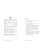
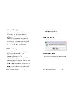
SW1 Setting: 

SW1 

Key 

1 2 3 

RS-232 ON 

OFF 

OFF 

RS-422 

OFF OFF OFF -  - 

RS-485 OFF 

ON 

ON 

- - 

Normal 

 - - - 

OFF 

OFF 

DHCP     

OFF 

ON 

Default     

ON 

OFF 

Console    

ON 

ON 


Normal

: Aport is in Normal Operation Mode 

DHCP

: Network IP Address is assigned by DHCP Server 

Default

: All the settings are reset to Factory Default.     

Console

: COM1 serial port is served as console port.    User can 

use ACSII command to configure BWS-136 via COM1 port.   

Please refer to Appendix I for the ASCII command 


Changing the switch settings will not be effective until 

system reboot by pressing RESET button 


BWS-136 User Manual_amend.doc


- 10 -


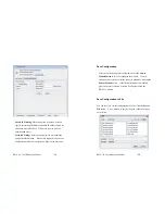
LED Status 

The LED provides the BWS-136 operation information.    The 

LED status is described as follow: 


Power LED: Power LED keeps ON if power (+9VDC to +40VDC) 

is correctly input to BWS-136. 

Ready LED: Ready LED keeps ON when Aport 211 firmware is 

ready for operation.    Ready LED will be flash when Aport 211 in 

Serial Console mode (SW1 key 4 and key 5 are ON) or Telnet 

Console mode (Telnet Console port:5001 are connected) 

Link/Act LED: Link and Activity LED will turn ON when the 

Ethernet cable is connected.    When there is network data traffic, 

this LED will be flash. 

RX/TX LED: The RX/TX LED is a dual color LED that indicates 

the serial data traffic.    In RS-232 mode, the Yellow LED stands 

for transmitting data and Green LED means receiving data.    In 

RS-422/485 mode, the Yellow LED stands for receiving data and 

Green LED means transmitting data. 

Summary of Contents for Network Device BWS-136

Page 1: ...ut 7 Connecting Power 7 Connecting Ethernet Port 8 Connecting Serial Port 8 Switch SW1 Settings 8 LED Status 10 Serial Port Pin Assignments 11 Factory Default Settings 13 Configure BWS 136 14 Install...

Page 2: ...g capability BWS 136 converts the serial data to standard TCP IP protocol therefore the serial device can be accessed everywhere via Internet or Ethernet In addition BWS 136 provides an embedded Web s...

Page 3: ...SD Digital Input Output General Purpose DIO x8 DIO0 to DIO5 Programmable Digital I O TTL DIO6 to DIO7 Programmable Digital I O CMOS BWS 136 User Manual_amend doc 6 Software Protocol TCP IP HTTP ICMP D...

Page 4: ...to the Ethernet port of BWS 136 The Link Activity light will keep solid yellow color if Ethernet cable is corrected to the network and this light will keep flashing if there are data transmitted Conn...

Page 5: ...s The LED provides the BWS 136 operation information The LED status is described as follow Power LED Power LED keeps ON if power 9VDC to 40VDC is correctly input to BWS 136 Ready LED Ready LED keeps O...

Page 6: ...Data 4 DTR RxD Data 5 GND GND GND 6 DSR 7 RTS 8 CTS 9 BWS 136 User Manual_amend doc 12 Digital I O Digital I O uses DB9 connector and the pin assignments are described as follow Pin 1 DIO4 Pin 2 DIO3...

Page 7: ...Data Format N 8 1 Parity Data bits Stop bits Flow Control None Interface RS 232 BWS 136 User Manual_amend doc 14 Configure BWS 136 Aport 211 provides four ways to configure the settings They are 1 Ja...

Page 8: ...address of the module you can click Search by IP item and specify the IP address to find the BWS 136 User Manual_amend doc 16 BWS 136 The default IP address of BWS 136 is 192 168 16 10 Click on the r...

Page 9: ...IP Address TCP port and operation mode as follow OpMode TCP operation mode setting TCP Port TCP Port number of BWS 136 Destination IP The IP address of remote host which BWS 136 will actively connect...

Page 10: ...on Pages in the next entry BWS 136 User Manual_amend doc 20 Save Configuration After the all the settings are configured click to the Save to Module button to save the settings to the module The new s...

Page 11: ...BWS 136 by using the Import button BWS 136 User Manual_amend doc 22 4 Web Configuration Overview BWS 136 can also be configured by Web Browser The build in Web server and Web configuration pages makes...

Page 12: ...nd doc 24 Customize Your Web Page After you complete your web page design you can use the Manager Utility manager jar to upload the Web page to bws 136 Web server The web files need to be converted to...

Page 13: ...er can use serial terminal or Telnet command to configure BWS 136 when Web browser and Java utility are available In addition these functions provide user the most convenient way to develop their own...

Page 14: ...nd format is as follow LOG 16 bytes of TEA Encrypted Password or LOG if there are no password settings BWS 136 User Manual_amend doc 28 Forgot Password If you forgot the Password you can switch SW1 to...

Page 15: ...136 User Manual_amend doc 30 RS 422 RS 485 G S LI IP Address e g SLI192 168 2 127 G S LN Netmask e g SLN255 0 0 0 G S LG Gateway e g SLG192 168 2 254 G S LC IP Mode 0 Static IP 1 DCHP G LM MAC Defaul...

Page 16: ...etting as Default setting System S EI Exit console DIO S DM Set Digital I O mode I Input O Output H pull high L pull low BWS 136 User Manual_amend doc 32 e g SDMI 0 4 5 set DIO0 DIO4 DIO5 as input SDM...

Page 17: ...dham of the Cambridge Computer Laboratory Placed in the Public Domain by David Wheeler and Roger Needham ANSI C VERSION New Variant Notes TEA is a Feistel cipher with XOR and addition as the non linea...

Page 18: ...igned long const v unsigned long const w const unsigned long const k register unsigned long y v 0 z v 1 sum 0xC6EF3720 delta 0x9E3779B9 n 32 sum delta 5 in general sum delta n while n 0 z y 4 y 5 y su...

Reviews: