7. LED Description
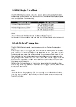
The following table describes th
e LED’s located on the POE200 Series media
converter.
LED
Colour
Function
FX LNK/ACT
Green
Lit when fibre connection is present
Blinks when fibre data is present
TP LNK/ACT
Green
Lit when TP connection is present
Blinks when TP data is present
TP SPD
Green
Amber
Green Lit when TP speed is 1000Mbps
Amber Lit when TP speed is 100Mbps
Off when TP speed is 10Mbps
PWR
Green
Lit when
5V power is applied
PoE PSE-TP
Green
Lit when PoE feeding power is active
Red
Lit when PoE feeding power is disrupted
(In case of overtemperature/overcurrent )
4W
Green
Light when PD Class Type is Class 1
7W
Green
Light when PD Class Type is Class 2
15.4W
Green
Light when PD Class Type is Class 0 or 3
8. DIP Switch and Reset Button
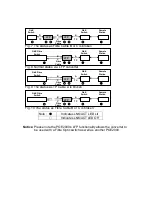
Reset :
Once S1-1, S1-2 is changed, please press this button to have
the settings take effect.
S1-1 Bridge mode : Cut through (default) or Normal
S1-2 LFP
: LFP enabled(default) or disabled
S1-3 PoE ON/OFF : Enable(default) or disable
Note:
1. S1-1 :
Cut through mode supports jumbo frame size up to 9216Bytes.
Normal mode supports frame size up to 2048 Bytes
2. S1-3 :
Must be set to PoE ON to supply power to PD device.
Fig. 11 Reset button and S1
—Bit 1, 2, 3 Configuration and Setting


