background image

13 

D: 

CONTROL AND AUXILIARY EQUIIPMENT 

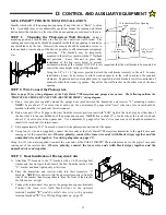
SAFE FINISH™ PHOTOSYSTEM INSTALLATION 


Identify which side of the garage door opening (if any) the sun is “likely” to shine 
into.  As sunlight may cause undesirable operation, mount the sending unit (black 
button below the window) on the side of the door opening exposed most to the sun. 


STEP 1:  Mounting the Photosystem Wall Brackets 


Select a 

mounting position 5 inches above the floor to the center line wall bracket.  The 
sending and receiving units should be mounted inside the door opening to minimize 
any interference by the sun.  However, the sensors should be mounted as close to 
the door track or inside edge of the door as possible to offer maximum entrapment 

protection.  The brackets may be temporarily 
mounted to the wall (or jamb) with the 1” flathead 
nail provided.  Leave this nail in place after 
installation of the lag screw below to prevent 
accidental rotation of the bracket  NOTE: It is very important that the wall brackets be mounted at 
exactly the same height so they will be aligned. 


Using the 1/4” x 1-1/2” lag screw provided, attach the wall bracket securely to the wall.  In some 
installations it may be necessary to attach wooden spacers to the wall to achieve the required 
clearance.  Expansion bolts (not supplied) may be required to attach brackets to walls constructed of 
materials other than wood or gypsum.  Repeat for the wall bracket on the other side of the door 
opening. 


STEP 2:


Wire Connect the Photosystem 


Refer to page 20 for wiring diagrams of the Safe Finish™ Photosystem and garage door opener.  The following outlines the 
“PHOTOCELL SERIES CONNECTION (RECEIVER FIRST)” wiring diagram. 

A. Run a wire pair (not supplied) around the garage door jamb between the transmitter and receiver "L" mounting brackets.   

NOTE:

 Leave about 12” of extra wire at each end. Use a minimum 22 gauge solid "trace" wire (one wire in set should be 

marked to identify it at each end) for interconnect. 

B. Run a wire pair (20 or 22 gage solid wire) from the receiver position (unit with "LED" light in the front, may be either side of 

the door) back to the rear bulkhead of the garage door opener.  

NOTE:

 Leave about 12” of extra wire at the receiver end and 

about 24” of extra wire at the opener end.  Use a minimum 22 gauge solid "trace" wire (one wire in set should be marked to 
identify it at each end) for interconnect. 

C. Strip approximately 5/16” from each wire end at the photosystem units and at the opener. 
D. Using two (2) wire nuts (supplied), connect the wire ends at the Safe Finish™ Photosystem transmitter to the pigtail wire ends 

coming out of the transmitter unit.  

Observe polarity, connect the trace wire ends (with black stripe) together and the 

unmarked wire ends together.  See wiring diagrams on page 20 .


Using two (2) wire nuts (supplied), connect the wire ends at the SAFE FINISH™ Photosystem receiver to the pigtail wire ends 
coming out of the receiver unit.  

Observe polarity, connect the trace wire ends (with black stripe) together and the 

unmarked wire ends together. 
 

STEP 3

 Final Installation of Photosystem Units 


A. Attach the"U" brackets to the "L" brackets with a 1/4-20 carriage bolt, 

washer and hex nut (provided). Insert the bolt from the inside of the 
"U" bracket and hand tighten only at this time. 

B. Place the transmitter and receiver units into their respective "U" 

brackets.  

NOTE:

 It is easier to slip the photosystem units in from the 

side of the bracket than forcing them in from the front of the bracket.  

See Illustration, at right.


C. Connect the interconnect wire pair to the garage door opener terminals. 

Connect the trace wire (with black stripe) to the operator 
terminal marked 

“4” 

and the solid color wire to the operator 

terminal marked 

“5”

. See Wiring Diagrams on  page 20 .


104382 

104383 

1/4” x 1-1/2” 

Lag Screw 

5 Inches 

Above the Floor 

#8 Hex 

Head 

Screw 

12 Inches From Door Opening 

110052-1 

Summary of Contents for CHALLENGER AC9000 Series

Page 1: ...READ THIS MANUAL READ THIS MANUAL READ THIS MANUAL CAREFULLY BEFORE CAREFULLY BEFORE CAREFULLY BEFORE CAREFULLY BEFORE INSTALLATION OR USE INSTALLATION OR USE INSTALLATION OR USE INSTALLATION OR USE...

Page 2: ...HANICAL hazard of INJURY OR DEATH Gives instructions to avoid the hazard CAUTION CAUTION CAUTION CAUTION Indicates a MECHANICAL hazard of DAMAGE to your door door operator or equipment Gives instructi...

Page 3: ...d close travel mode the Opener will sense an obstruction and reverse the direction of the door In the open mode the Opener will stop Since all doors are different the Sensing System has independent ad...

Page 4: ...oor opener controls Always keep moving door in sight If person is pinned push control button or use emergency release Test door opener monthly Refer to your owner s manual Place one inch object or 2x4...

Page 5: ...guide tabs and the two rear bolt studs on the power head unit and place the rail chain assembly in place over the power head unit The power head drive unit limit lever protrudes up through the rail c...

Page 6: ...Y GOGGLES OR OTHER PROTECTIVE EYEWEAR IF POSSIBLE INSTALL THE DOOR OPENER 7zFT OR MORE ABOVE THE FLOOR MOUNT THE EMERGENCY RELEASE 6 FT ABOVE THE FLOOR REINFORCE LIGHTWEIGHT FIBERGLASS ALUMINUM AND ST...

Page 7: ...IL FOR DOOR HEIGHT UP TO 8 FT 104368 REINFORCE THE HEADER WALL Reinforce the header wall wall above the door opening as required to ensure rigid mounting of the front wall bracket Locate the vertical...

Page 8: ...EATH REINFORCE HEADER USING 2 x 6 WOOD STUDS AND LAG SCREW OR ANGLE IRON AND LAG SCREWS AS NECESSARY NOT PROVIDED WARNING WARNING WARNING WARNING 110049 Center of Door Front Wall Bracket 1 2 Above Hig...

Page 9: ...o ensure rail will be parallel with the direction of door travel Use supplied hangers from the ceiling beams to hang the opener at the power head end be sure to locate and mount to the solid structura...

Page 10: ...nd pull trolley toward the power head unit Now rotate the door arm tube section two turns counterclockwise increasing the exposed length of the door rod to provide a cushion when the door is closed or...

Page 11: ...train Relief It is not used with permanent wiring Using the two wires black white that were left when you cut off the line cord splice in the permanent connections Permanent Wiring Connection Normal C...

Page 12: ...he necessary connections to the operator terminal strip WARNING SOME LOCAL BUILDING CODES DO NOT ALLOW SURFACE WIRING BE SAFE AND CHECK WITH YOUR LOCAL BUILDING INSPECTOR FIRST STEP 4 Ensure power is...

Page 13: ...d Use a minimum 22 gauge solid trace wire one wire in set should be marked to identify it at each end for interconnect B Run a wire pair 20 or 22 gage solid wire from the receiver position unit with L...

Page 14: ...the position of the Transmitter in the car If the distance is still inadequate try bending the Antenna Wire to a different angle If the distance is still inadequate replace the Battery with a standar...

Page 15: ...D FOLLOW ALL USER SAFETY INSTRUCTIONS TURNING ON POWER TO THE OPERATOR NOTE It is now necessary to turn on the power in order to run the Opener to test the operation and check the limit settings Befor...

Page 16: ...s then shut off 3 Optional Wall Station adds the convenience of allowing the light to be turned on and stay on until turned off by a second push of the button or activation of door cycle If the light...

Page 17: ...everse in the close direction and stop in the open direction This must be adjusted so your opener does not use excessive force in the down direction or react to the weight of the door during upward tr...

Page 18: ...Piece Doors REPEAT THIS TEST MONTHLY Solid Test Object 110055 3 E OPERATION AND ADJUSTMENT INSTRUCTIONS Adjustment 4 Obstruction Sensing Closing Direction Your opener is designed to automatically reve...

Page 19: ...ect must prevent an open door from closing in any other mode other than constant pressure on the wall button The object should also cause a closing door stop and reverse to the open position If it doe...

Page 20: ...e Finish Photosystem beam see Important Test Photoelectric Obstruction Test page 19 3 Manually operate the door ensure door is in the closed position before attempting to engage manual operation see C...

Page 21: ...USHBUTTON STATION IS IN SUCH A POSITION AND OF SUCH A HEIGHT THAT IT CAN ONLY BE ACTUATED BY AN ADULT OF AVERAGE HEIGHT THE CAUTION LABEL IS PROMINENTLY DISPLAYED NEXT TO THE PUSH BUTTON OR WALL STATI...

Page 22: ...force improperly adjusted 14 Down sensitivity force improperly adjusted 15 Bottom of door frozen to ground 16 Ice and snow built up under door 17 Floor risen or sunk from weather change 18 Someone in...

Page 23: ...r L H 2 198077 Trolley Assembly 3 221020 Trolley Wing Foot 4 220961 Nylon Button 5 252109 Chain Latch Assembly 6 009224 3 pc Chain Master Link 7 009011 Chain specify length 8 160366 Limit Stop 9 22096...

Page 24: ...epair within the warranty period which upon receipt by Allstar are confirmed to be defective and covered by this limited warranty will be repaired or replaced at Allstar s sole option at no cost and r...

Reviews: