1. Setting Tension on Primary Chain
The Primary Chain Preload tension is set by adjusting the upper spring seat
above the tensioner arm. The spring assembly is fitted with an adjustment
indicator which uses the upper edge of the spring as its marker. When it aligns
with the green or “OK” portion of the decal then the tension is set correct and
does not require adjustment. But if the upper edge of the spring is outside this
section, in the red, then adjustment is required. The decal arrow indicates the
direction in which to adjust.
The Upper spring seat is an internally threaded sleeve which sits on guide
shaft. It has a shoulder for the spring to seat against and a 40mm A/F hexagon
section at the top for adjustment. A standard M20 nut is used to lock the seat in
position.
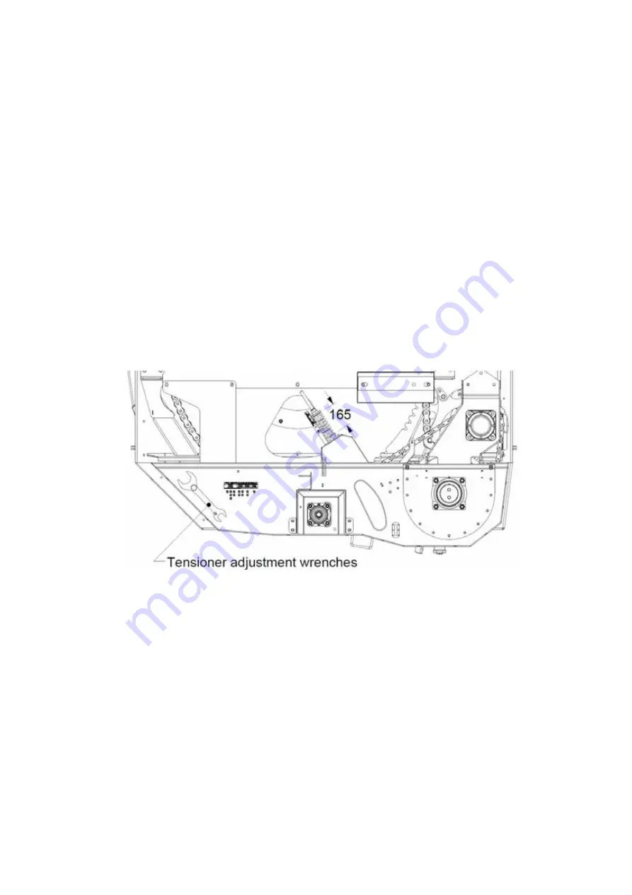
To adjust first remove the 2 wrenches from their storage location on the front
right face of the drive system reduction gearbox. (see Figure 31).
Swing the tensioner indicator downwards to allow full access to the spring seat
nuts. Using the 40mm wrench & a 30mm wrench open the locknut (top nut) and
screw clear of the spring seat. The spring seat can now be adjusted up or down
to set the compressed length to 165mm (Its free length is 200mm). The upper
edge of the spring should now be positioned in the centre of the green section
of the indicator. This provides the correct tension of approx. 70kg to the chain.
To lock the setting, hold the spring seat in position with the 40mm wrench and
tighten the locknut against it with the 30mm wrench.
Figure 31: Storage position of Tensioner Adjustment Wrenches & Primary Chain
Tensioner Spring setting
2. Setting Tension on Secondary Chain (Rotor Chain)
The tension is set by adjusting the upper spring seat above the tensioner arm.
The spring assembly is fitted with an adjustment indicator which uses the upper
edge of the spring as its marker. When it aligns with the green or “OK” portion of
the decal then the tension is set correct and does not require adjustment. But if
the upper edge of the spring is outside this section, in the red, then adjustment
is required. The decal arrow indicates the direction in which to adjust.
33
Revision A04 July 2018
Summary of Contents for KEENAN MechFiber345
Page 2: ...CONTENTS 2 Revision A04 July 2018 ...
Page 50: ...8 2 Chassis Parts 50 Revision A04 July 2018 ...
Page 52: ...8 3 Front Cover Parts 52 Revision A04 July 2018 ...
Page 54: ...8 4 Standard Feedout Tray Parts 54 Revision A04 July 2018 ...
Page 56: ...8 5 Fold Down Tray Parts Optional Extra Option 56 Revision A04 July 2018 ...
Page 57: ...57 Revision A04 July 2018 ...
Page 64: ...8 10 Driveline Parts 64 Revision A04 July 2018 ...
Page 65: ...65 Revision A04 July 2018 ...
Page 82: ...14423 akgraphics ie keenansystem com KEENAN System KEENANsystem ...


