background image

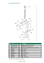
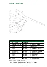
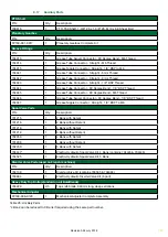
Item:

P/N:

Qty: Description:

19

705019

1

Rotor drive chain - ASA160SH, 119 p joiner link 

(Sapphire)                                                     

704189

1

Rotor drive chain - ASA160SH, 119 p joiner link 

(Diamond)                                           

20

705029

1

Joiner link - ASA160 – 1 pitch - slip fit (Sapphire)

704099

1

Joiner link - ASA160 – 1 pitch - slip fit (Diamond)

21

FP160-007-0013

1

Front rotor spacer

22

EF207-34

1

Rotor Sprocket - 104-tooth ASA160

23

FP160-007-0037 2

Rotor front cover assembly (Auxiliary & square seal)

24

FP280-048-0445

1

Rotor chain tensioner pivot pin assembly

25

FP380-048-0046

1

Rotor chain tensioner arm assembly 2

26

FP200-048-0251

1

Rotor chain tensioner compression spring & seat assembly

27

FP200-009-0025

1

Auger front cover - Lower plate

28

FP200-009-0026

1

Auger front cover - Upper plate

29

703753

1

F516A bearing housing & cover

30

701457

1

H316, 70mm bore adaptor sleeve, ring nut & castellated 

washer

31

704122

1

Bearing spacer ring, SR140 x 10

32

700847

1

22216K bearing insert

33

700281

1

M16 x 90mm Bolt

34

FP280-048-0452

1

Rotor drive chain tensioner wear block

35

700283

3

M16 Lock nut

36

FP380-048-0043

1

Rotor chain tensioner arm assembly 1

37

FP200-048-0252

1

Rotor chain tensioner spring seat shaft assembly 

(345/365/380)

38

704196

1

Compression spring - 12mm wire, 80mm OD, 280mm long

39

FP160-048-0148

1

Chain tensioner lower spring seat

40

FP160-048-0147

1

Chain tensioner lower spring seat locking nut

41

705862

1

M16 x 175mm bolt

42

FP160-048-0145

1

Chain tensioner lower spring seat adjuster tube assembly

43

700246

2

M12 x 25mm setscrew

44

FP280-048-0395

1

Idler shaft thrust washer

45

FP280-048-0396 6

Idler shaft thrust shim (2mm)

46

FP200-048-0160

1

X18 steel housing bearing with bearing puller shoulder plate

47

FP200-048-0162

1

Idler shaft front bearing mounting plate assembly

48

FP280-048-0386

1

Front idler bearing bolt positioning ring assembly

49

FP200-037-0071

1

PTO guard – MF345/MF365

50

FP160-048-0194 8

Bearing bolt hole reducer & collar (FYH bearing)

51

705145

2

FYH UCF308 40mm bearing with cast 4-bolt flange housing

52

700628

1

Z6 Spline shaft with 8-tooth ASA120 Sprocket

53

FP200-048-0153

1

Idler shaft assembly 2

54

705828

1

Oil Level window

67

Revision A04 July 2018

Summary of Contents for KEENAN MechFiber345

Page 1: ...Operator s Manual MechFiber345 MechFiber365 Effective from models MF345I100 MF365I130 KEENAN MechFiber345 MechFiber365 OM Publication Date A04 July 2018 EN ...

Page 2: ...CONTENTS 2 Revision A04 July 2018 ...

Page 3: ...Maintenance advice 28 6 2 Maintenance Checklist 29 6 3 Chains 30 6 4 Oil level 32 6 5 Chain tensioning 32 6 6 Greasing 35 6 7 Blade Maintenance 38 6 8 Maintenance for baleblend models 38 6 9 Shear bolts 40 6 10 Nuts and bolts 40 6 11 Tyres 41 6 12 Wheels 41 6 13 Rear feedout elevator where fitted 42 6 14 Side stub feedout elevator where fitted 42 6 15 Axle maintenance 44 6 16 Machine storage 45 7 ...

Page 4: ...e and time again This ability is the cornerstone of the KEENAN MechFiber System delivering improved efficiency and profitability on the farm More recently the BaleBlend models have introduced the ability to handle bales of all sizes and types The minimum moving parts ensure a robust machine with high mechanical efficiency Simple routine maintenance and correct operation will deliver many years of ...

Page 5: ...edge of the machine and are aware of the possible risks Proper use requires strict adherence to the instructions in the operators manual It is up to the user and the owner to comply with the instructions for accident prevention as well as general rules on safety occupational health and road legislation 1 3 Ordering This Manual You can order this operators manual by sending a request to Alltech Far...

Page 6: ...of serious dangers possibly involving accident or injury CAUTION Texts with this symbol draw your attention to a possible risk of damage to your KEENAN MechFiber Mixer Wagon Failure to observe the information contained in a caution may invalidate your warranty Note Texts with this heading give general information which improves the operation efficiency of your KEENAN MechFiber Mixer Wagon 2 Identi...

Page 7: ...4 Stands 5 Feed out tray 6 Lighting 7 Load bumper optional 8 Top knife 9 Bale Blender cradle arm optional 10 VFC door 11 Auger 12 Body blades 13 Chassis wheels 14 Paddle 15 Rotor 16 BaleBlend optional 16 8 9 10 11 12 13 14 15 Table 1 Figure 2 7 Revision A04 July 2018 ...

Page 8: ...Grams 3 Axle weight in Kilo Grams 4 Hitch weight in Kilo Grams 5 Year of Manufacture 6 Machine serial number Table 2 Figure 3 Figure 5 Figure 6 Serial number plate is located on the front left hand drive system cover Figure 4 Plate mounted on chassis right hand side 1 2 3 5 4 6 8 Revision A04 July 2018 ...

Page 9: ... Plate Type 2 Reference Description 1 Axle type 2 Brake Type 3 Homologation number CEMAGREF 4 Loads 5 Homologation number TUV Speed load 6 Axle code 7 Order Number 8 Identification plate number Figure 7 Figure 8 Figure 9 Table 3 9 Revision A04 July 2018 ...

Page 10: ...n a single axle Information Complete the column with the requested information Machine Type Serial Number Year of Manufacture Options Date of First use Dealer name Dealer Address Dealer Telephone number 2 4 Specifications Model MechFiber345 MechFiber365 Single Axle Tandem Axle Single Axle Tandem Axle Unladen kgs 8 450 9 850 10 200 10 950 lbs 20 062 21 715 22 481 24 134 Payload kgs 6 000 6 000 8 00...

Page 11: ... unauthorised by KEENAN H Any machine fitted with spurious or non genuine spare parts and attachments or spare parts or attachments not approved by the Company I Any machine damaged in transit whilst being loaded or unloaded on premises other than those owned by the Company J Parts which may be defective or which may have failed and which are not retained on site pending further investigation by t...

Page 12: ...mals or objects f Do not stand between the tractor and mixer wagon while it is in use g Use only a PTO shaft with a properly fitted safety guard and correct shear bolt h Always connect the PTO shaft with the shear bolt end to the machine The operating speed of the PTO is 540 rpm and the direction of rotation is marked on the front cover Always use a well maintained PTO shaft and keep the safety co...

Page 13: ... In the event that the Breakaway Safety Brake device has been activated or damaged it is recommended that KEENAN Service are contacted for directions to reset u Routine cleaning may be carried out using a power washer Isolate any power sources before beginning If washing the inside the Mixing Chamber open the drain bung underneath the body to allow water escape Always disconnect PTO shaft from the...

Page 14: ...safety beading that is provided for the top knife Figure 3b Top Knife Protection Figure 12 Top knife Protection Figure 10 Body blade and blade cover 7 Use a suitable secure ladder for access to and from the mixer wagon Note The ladder at the rear of the machine is provided as a means of viewing the ration only and should not be used as a means of access the mixing chamber 8 Always maintain 3 point...

Page 15: ...chine WARNING The operator is responsible for the safe operation of the machine at all times This machine should only be operated by one person at all times The machine should never be left unattended during operation WARNING The Breakaway Safety Brake Device should be attached to the tractor at all times 1 2 3 4 9 10 6 7 Operator Manual 15 Revision A04 July 2018 ...

Page 16: ...ore using the machine Shut off the engine and remove the key before performing maintenance or repair work on the machine Never reach into the rotating auger Danger of entrapment Do not ride on the platform or ladder Look out for overhead power lines Apply the handbrake when parked Do not stand between the tractor and mixer wagon while it is in operation 1 5 9 2 6 10 3 7 4 8 16 Revision A04 July 20...

Page 17: ...oreign objects have been removed No damage has occurred during transport Check the weighbox and ensure the power lead from the weighing system is either connected to the tractor battery via a direct fused line 7 pin plug or to a 12v battery located in the side box of the feeder To zero the weighbox press and hold the zero and minus keys together and hold until end appears on the screen then releas...

Page 18: ...st feed pipe and so seals and or the valve chest itself may be damaged if oil flows in the wrong direction through the chest Typically the hydraulic return pipe on the valve chest is fit with a one way flow valve to prevent oil being fed to the valve chest in the wrong direction This is identifiable as a steel connection on the end of the pipe with an arrow stamped on its side to indicate the dire...

Page 19: ...re resistant to frost and corrosion The unit should however not be directly exposed to a high pressure water jet The weigh box unit may vary from model to model and region to region A separate manual is supplied for your weigh box unit which you should refer to for specific operating instructions 5 3 Hitch Height Adjustment The KEENAN MechFiber345 KEENAN MechFiber365 hitch has been designed to all...

Page 20: ...ned from the machine Mechanical failure will result Due to the nature of the loading this may occur at load levels below that necessary to break the shear bolt CAUTION The machine can be overloaded before the shear bolt breaks Therefore not breaking a shear bolt is not an indication that the machine is not being overloaded The overall amount of material that can be chopped mixed in one load depend...

Page 21: ...nt of the blades ensures the materials reach optimum size length without grinding it down and destroying the all important scratch factor of the forages producing a MechFiber mix Mixing time will be determined by the required chop length Follow procedures contained in this manual or consult your KEENAN Physical Nutritionist for further information For BaleBlend models do not load a complete 6x4 ro...

Page 22: ...mbling action will not take place correctly In addition to reducing mix quality it increases the horsepower requirements and reduces the life of the machine The effectiveness and speed of chop is determined by The number of effective sharp and intact blades The dry matter of the material to be added The amount of pre chopping of material The loading sequence The total amount of material to be chop...

Page 23: ... out rate 1 Ensure that the VFC door is still closed 2 Re engage the tractor PTO at idle increasing engine revs to between 1 400 and 1 600 rpm to achieve a paddle running speed of 6 8 rpm Allow the TMR to loosen and tumble for 15 20 seconds 3 Slowly open the VFC door to maximum of way then allow at least 1 minute before opening the door fully 4 Select a ground speed to feed out at an even rate alo...

Page 24: ...trate feeds along the length of the machine Load forages to the front back and centre of the unit in alternate grabs during the mixing Remove all twine wrap or polythene from bales Round or square bales should be split or broken into 4 pieces minimum Use front grab or forks as required Stop PTO before moving to feed out area Mixing time will depend on chop length required Order Speed Feed Ingredie...

Page 25: ...D MIXING SEQUENCE Set paddles running at 6 8 RPM for all bale types Note When chopping straw higher revs can be used Load round bales to the centre of the unit with the flat end towards the top knife Allow minimum of 2 minutes for previous bale to chop down before adding another CAUTION Do not load more than one bale at a time Stop PTO before moving to feed out area Mixing time will depend on chop...

Page 26: ...he bale and the behaviour of the bale when it is being chopped 7 When loading large square bales the method is to load the bale so that the sections lie across the tines so as to prevent the sections falling through the gap in the tines see diagram to the right sections of large square bale loaded perpendicular to the tines The easiest way to do this is to load the bale in two halves on the loader...

Page 27: ...he water to drain off 3 It may be necessary to repeat this if materials being chopped are particularly dirty 4 Chop the materials by running the machine at 8 revs For low usage best results are achieved by chopping sufficient material for 2 days 5 11 Lifting Hooks Anchoring Points CAUTION Lifting and support equipment accessories must be compliant and controlled in accordance with the regulations ...

Page 28: ...N MechFiber Mixer Wagon has been designed for optimum performance with a minimum of maintenance Chains bearings and grease points have been kept to a minimum without compromising function All components are of high quality and provide excellent durability Regular routine maintenance will ensure your KEENAN MechFiber Mixer Wagon gives you the best results with a minimum of problems WARNING Prior to...

Page 29: ...n total Tandem axle where fitted Grease all 14 pivot points listed below 2 on each brake rod 8 in total 1 on each brake arm 4 in total 1 on each spring bogie pivot pin 2 in total Axle U bolts Check axle U bolt torque settings tandem only Tyres Check that tyres are inflated to the recommended pressures and make sure the wheel nuts are tight Monthly BaleBlend Grease each Tine pivot check the Tines f...

Page 30: ...Chains Figure 28 Drive System overview Each week check the condition of the chain tension arms and adjust as required There are two chains used on the KEENAN MechFiber345 MechFiber365 models The primary drive chain ASA120 drives the idler shaft and the auger shaft from the input shaft see figure 28 and the secondary chain ASA160SH drives the rotor Both chains are tensioned by spring assemblies on ...

Page 31: ...in bedding in period it is recommended to check chain tension daily See next section Figure 29 Chain joiner link Primary Drive Chain ASA120 Links 92 inc joiner Pitch mm 38 1 Pitch inches 1 5 Chain length mm 3 505 Chain length inches 138 Rotor drive chain ASA 160 Links 120 inc joiner Pitch mm 50 8 Pitch inches 2 Chain length mm 6 096 Chain length inches 240 Table 10 MechFiber345 MechFiber365 drive ...

Page 32: ...ng of 150mm2 s 40 C Do not use grease on the chains as it is unsuitable for the application and will not allow lubrication of the vital internal parts of the chain Figure 30 MechFiber345 MechFiber365 Oil Level 6 5 Chain Tensioning With use the drive chains will extend slightly over time To compensate for this all KEENAN MechFiber machines are fitted with a tensioner mechanism on the slack side of ...

Page 33: ...s to the spring seat nuts Using the 40mm wrench a 30mm wrench open the locknut top nut and screw clear of the spring seat The spring seat can now be adjusted up or down to set the compressed length to 165mm Its free length is 200mm The upper edge of the spring should now be positioned in the centre of the green section of the indicator This provides the correct tension of approx 70kg to the chain ...

Page 34: ...the locknut upper nut and screw clear of the spring seat The spring seat can now be adjusted up or down to set the compressed length to 250mm Its free length is 280mm The upper edge of the spring should now be positioned in the centre of the green section of the indicator This provides the correct tension of approx 360kg to the chain To lock the setting hold the spring seat in position with one of...

Page 35: ...nt 4 Idler shaft bearing rear see figure 34 35 Grease point 5 Auger bearing front see figure 34 35 Grease point 6 Rotor bearing front see figure 34 35 Grease point 7 Primary drive tensioner sprocket see figure 34 35 Grease point 15 Rotor bearing rear see figure 36 Grease point 14 Auger bearing rear see figure 36 After every 40 hours of operation apply grease to the following pivot points through g...

Page 36: ...Figure 34 Grease points on central greasing manifold Figure 35 Drive system bearings pivot grease points 36 Revision A04 July 2018 ...

Page 37: ...Figure 36 Rear bearings VFC Door pivot grease points Figure 37 Single axle chassis grease points 37 Revision A04 July 2018 ...

Page 38: ...e is fitted to the head of each M24 tine bolt The following maintenance points should be checked on a monthly basis 1 Apply grease to each of the Tine Bolt grease points individually 2 The M24 tine bolt lock nuts should be checked for tightness they should be tight enough to prevent the tine from having any side movement but allow it fall under its own weight when let drop 3 The rubber buffer shou...

Page 39: ...to prevent material sitting on the top knife of the machine preventing a build up of material getting under the creel and damaging it as it is lowered To prevent damage to this rubber do not drop material on it from a height when loading material onto BaleBlend arms BaleBlend Attachment 39 Revision A04 July 2018 ...

Page 40: ...validate your warranty Table 11 Shear bolt size grade 6 10 Nuts And Bolts 1 After the first day and regularly thereafter inspect wheel nuts and tandem axle U bolts where fitted 2 After the first week and each week thereafter check all nuts and bolts including bearing nuts for tightness General Torque Stud Bolt type FT LB N M M22 335 450 M20 260 350 M18 200 270 U Bolt Diameter mm Tightening Torque ...

Page 41: ...e shoes springs studs and all other internal parts 3 Replace worn parts re grease and refit Note When re fitting the wheels tighten the castle nut until resistance is felt do not over tighten Release the castle nut 1 6 of a revolution check for movement in the hub and if none re fit the split pin Changing a wheel Park the mixer wagon on level ground and apply the handbrake Fit chocks to opposite w...

Page 42: ...ion properly Refer to the Rear Feedout Operator Manual Supplement for spare parts maintenance and operation Figure 42 Rear feed out elevator grease point 6 14 Side Stub Feedout Elevator Where Fitted An elevator system requires regular maintenance in order to achieve optimum performance Every week the elevator needs to be checked to make sure that the belt is running straight and not wearing uneven...

Page 43: ...Figure 43 Side Elevator greasing points Figure 44 Stub Elevator greasing points 43 Revision A04 July 2018 ...

Page 44: ... damaged must be replaced immediately to avoid dirt penetrating into the hub which can cause damage to the bearings Check hub caps are always in place and that they are in a good condition If the hubcaps are a press fit check visually they are fully home If the hubcaps are attached using screws fit a new gasket if needed once the hubcap is removed Retighten the screws regularly every 6 months The ...

Page 45: ... the machine down thoroughly preferably using a power washer 3 Retract the cylinder rods to protect them from moisture 4 Repaint the areas where the paint is no longer present 5 Lubricate according to the maintenance plan given in this manual 6 Place the machine onto axle stands to relieve the tires Use standard support stand systems and secure to prevent any risk of accident due to unstable riggi...

Page 46: ...the feed out door to avoid huge load on machine especially after feed has settled in body of machine Run machine slower For non BaleBlend models never load bales directly down on paddle in one go always chop up into at least 4 pieces 6 Noisy operation Check drive system oil level Check adjust chain tension Grease all tensioner pivot points Check chain alignment 7 Feed is not mixed properly Insuffi...

Page 47: ...e height settings Ensure all feed materials are free from foreign objects before loading into machine In the unlikely event of a large blockage occurring which prevents the machine from restarting using the tractor it may be necessary to enter the mixing chamber to manually clear the blockage Please refer to Section 4 Safety in particular point u 16 Blockage at auger Use VFC door to meter material...

Page 48: ...ely If the machine is new or the weighbox has been replaced it is possible that the weighbox may have the incorrect calibration code for the model Contact KEENAN service who can go through the procedure to check or alter the code If you suspect that the system is weighing inaccurately check all four weighcells to make sure that they are mounted correctly If the bolt through the weighcell has come ...

Page 49: ...e assembly 4 705808 705810 1 T Connector to VFC door hydraulic hose assembly 5 701510 701513 1 VFC Door Ram to VFC door Ram hydraulic hose 6 705806 705806 1 T Connector 7 705812 705812 1 1 4 BSP female hydraulic cap 8 703591 703591 Feed out Tray Hydraulic Ram Keen 63 9 704955 704955 VFC Door Front Ram Keen 52 10 704954 704954 VFC Door Rear Ram Keen 51 11 FP160 001 0095 FP160 001 0095 1 Hydraulic h...

Page 50: ...8 2 Chassis Parts 50 Revision A04 July 2018 ...

Page 51: ...154 1 Towing Eye Bush 32 5mm ID 702324 1 Towing Eye Bush 30mm ID Item P N Qty Description MechFiber345 MechFiber365 1 FP170 001 0097 FP170 001 0097 2 Hitch Eye Assembly 2 701952 701952 1 385 65 R 22 5 Wheel Tyre assembly 703934 703934 1 385 55 R 22 5 Wheel Tyre assembly 704570 704570 1 305 55 R 22 5 Wheel Tyre assembly 702879 702879 1 285 70 R 19 5 Wheel Tyre assembly 703860 703860 1 445 65 R 22 5...

Page 52: ...8 3 Front Cover Parts 52 Revision A04 July 2018 ...

Page 53: ...as Strut CA102911 600mm open 200N 250 Stroke 16 706086 1 A4 Flat Document Box 17 FP200 038 0032 1 MF345 365 GRP front cover Left side 18 FP200 037 0097 2 MF345 MF365 Front cover inner seal 19 FP200 038 0034 1 MF345 MF365 Front cover outer seal Right Side 20 700241 16 M10 Locknut 21 700729 16 M10 flat washer 22 FP200 037 0064 4 Front cover hinge mount assembly 23 FP380 037 0057 4 GRP hinge adjustme...

Page 54: ...8 4 Standard Feedout Tray Parts 54 Revision A04 July 2018 ...

Page 55: ...7 M16 Flat Washer 15 700736 6 M8 Flat Washer 16 700223 26 M8 NyLock Nut 17 700210 2 M8 x 25 Set Screw HT 18 700249 4 M12 x 35 Set Screw 19 700208 4 M8 x 20 Set Screw 20 702111 2 M10 x 30 Set Screw 21 700729 6 M10 Flat Washer 22 700266 4 M12 Lock Nut 23 700241 2 M10 Lock Nut 24 700730 2 M12 Flat Washer 25 700275 2 M16 x 50 Bolt 26 700283 4 M16 Lock Nut 27 700281 2 M16 x 90 Bolt 28 FP160 006 0124 1 ...

Page 56: ...8 5 Fold Down Tray Parts Optional Extra Option 56 Revision A04 July 2018 ...

Page 57: ...57 Revision A04 July 2018 ...

Page 58: ...ut 14 700250 9 M12 x 40 Set Screw 15 700266 9 M12 Lock Nut 16 700280 1 M16 x 80 Bolt 17 700268 1 M16 x 100 Bolt 18 700283 5 M16 Lock Nut 19 700302 1 M20 x 90 Bolt HT 20 700305 3 M20 Nylock Nut 21 700729 1 M12 Locknut 22 700730 18 M12 Flat Washer 23 700732 7 M16 Flat Washer 24 700733 3 M20 Flat Washer 25 701488 2 M20 x 110 Bolt HT 26 700226 1 M10 x 30 Cup Head Bolt 27 700269 1 M16 x 110 Bolt 28 700...

Page 59: ...160 006 0418 1 Fold Down Tray Shelf Assembly 47 FP160 006 0421 1 Fold Down Tray Shelf Top Plate 48 700208 4 M8 x 20 Set Screw 49 700223 4 M8 Nylock Nut Table 20 Feed Out Tray details Both MechFiber345 MechFiber365 Note Complete Fold Down Tray Kit Standard P N FP160 006 0416 Complete Fold Down Tray Kit OE 100 P N FP160 006 0423 Fold Down Tray can be supplied with the Magnet Assembly P N FP170 006 0...

Page 60: ...per bar 4 706006 1 Rear LED Light cluster Right Side 5 706005 1 Rear LED Light cluster Left Side 6 705879 2 LED Licence Plate Light 7 702294 1 UCF X18 90mm Bearing Assembly 8 700842 1 UCF X14 70mm Bearing Assembly 9 701274 1 Rear Rotor Bearing Cover 10 701273 1 Rear Auger Bearing Cover 11 FP160 003 0015 1 Rear bearing access slot cover plate 60 Revision A04 July 2018 ...

Page 61: ...m 3 FP380 037 0082 1 Weight display box mounting bracket 4 704140 2 Weigh cell 2 1 2 dia 5 2m cable DG 969 0076 5 704141 2 Weigh cell 2 1 2 dia 10 7m cable DG 969 0077 6 EF201 12 4 Weighbar bracket assembly 7 701496 4 M20 x 120mm bolt 8 8 grade 8 700305 4 M20 Locknut Table 22 Weighing System 61 Revision A04 July 2018 ...

Page 62: ... 010 0015 FP160 010 0015 4 VFC door front end guide collar wear washer 6 FP160 010 0014 FP160 010 0014 2 VFC door front end guide collar 7 701504 701504 2 VFC door centre stepped collar 8 702453 702453 2 17mm ID x 50mm OD x 4mm thick flat washer 9 701519 701519 2 M16 x 30mm setscrew 10 700279 700279 2 M16 x 75mm bolt 11 703148 703148 2 M16 x 40mm setscrew 12 700283 700283 4 M16 locknut 13 700732 7...

Page 63: ...FC door indicator cover 3 FP300 010 0013 1 VFC door indicator cover 4 703625 1 8 Expansion spring 22mm OD 2mm wire diameter 5 RD8010 61 1 VFC door indicator slider assembly 6 701559 4 Pulley Wheel 50mm OD x 20mm thick 7 FP280 006 0179 2 VFC door indicator cable access slot cover plate 8 FP200 006 0385 1 VFC door indicator cable cover plate 63 Revision A04 July 2018 ...

Page 64: ...8 10 Driveline Parts 64 Revision A04 July 2018 ...

Page 65: ...65 Revision A04 July 2018 ...

Page 66: ...l collector tray assembly 10 FP200 048 0193 1 Primary drive chain inner oil baffle assembly 11 FP200 048 0245 1 Auger Flange Baffle Plate 12 FP200 048 0227 1 Primary drive chain outer oil baffle assembly 12a FP200 048 0307 1 Primary Drive Chain outer oil baffle scraper plate assembly 13 FP200 048 0194 1 Primary drive chain outer oil baffle lower retaining washer 14 704188 1 Primary drive chain ASA...

Page 67: ...or drive chain tensioner wear block 35 700283 3 M16 Lock nut 36 FP380 048 0043 1 Rotor chain tensioner arm assembly 1 37 FP200 048 0252 1 Rotor chain tensioner spring seat shaft assembly 345 365 380 38 704196 1 Compression spring 12mm wire 80mm OD 280mm long 39 FP160 048 0148 1 Chain tensioner lower spring seat 40 FP160 048 0147 1 Chain tensioner lower spring seat locking nut 41 705862 1 M16 x 175...

Page 68: ...ting indicator assembly 2 69 704914 13 Grease tube connector straight M6 thread 70 704947 13 Adaptor 1 8 BSP external to M6 internal to 1 8 BSP internal 71 701129 13 1 8 BSP grease nipple 72 FP160 048 0175 2 70mm 40mm spring seat spanner 73 704439 1 M8 star control knob 74 700298 8 M20 x 70mm Bolt Grade 8 8 75 FP160 048 0064 1 48 tooth ASA120 idler sprocket 76 FP200 048 0154 1 Idler shaft assembly...

Page 69: ...008 0009 6 Paddle rubber retainer N A FP200 008 0010 6 Paddle rubber retainer 7 700732 700732 56 78 M16 flat washer 8 700283 700283 56 78 M16 Nylock nut 9 701822 701822 2 Rotor Lip Seal Rubber 10 FP140 007 0017 FP140 007 0017 2 Braided Rotor Seal Rubber 11 FP140 007 0006 FP140 007 0006 2 Rotor Seal Retainer 12 701541 701541 1 Rotor Spacer 90mm ID x 120mm OD x 40mm long 13 FP160 007 0026 FP160 007 ...

Page 70: ...026 1 23 tooth ASA120 auger driven sprocket 3 FP160 009 0024 FP160 009 0024 1 Auger stub shaft assembly forged 4 700305 700305 16 M20 Locknuts 5 FP280 009 0070 FP280 009 0070 2 Auger Seal Rubber 6 FP280 002 055 FP280 002 055 2 Auger Seal Retainer 7 N A FP200 009 0031 1 Auger Assembly Table 27 Auger Assembly 70 Revision A04 July 2018 ...

Page 71: ...t and rear end seal 5 N A 704880 4 VFC door outer end seal rubber 6 FP140 006 0022 FP200 006 0076 6 VFC door shroud seal retaining flat 7 701195 701199 4 2 VFC door outer seal rubber 8 FP160 006 0093 FP160 006 0093 1 Auger chamber material deflector Table 28 Body Seal 8 13 Body Sealing Parts Note MechFiber365 uses 2 types of VFC door outer seals 701199 for the middle section of the auger chamber a...

Page 72: ...ody Blade 6 25mm thick 3 700226 700226 48 56 M10 x 30mm Cuphead bolt 8 8 grade 705405 705405 48 56 M10 x 40mm Cuphead bolt 8 8 grade 4 700241 700241 48 56 M10 hex nut 5 700737 700737 48 56 M10 Spring Washer Table 29 Blades There are 24 blades used as standard on the MechFiber345 and 28 as standard on the MechFiber365 Extra blades may be added depending on machine specification Used only in conjunc...

Page 73: ...same as 345 9 11 M24 Locknut 10 700316 same as 345 9 11 M24 Washer 11 FP200 045 0154 same as 345 9 11 Tine Arm Assembly 12 FP140 045 0004 same as 345 2 0 Retainer Strip 5mm for Rubber Apron 675mm Long 13 FP140 045 0003 FP200 045 0003 1 Rubber Apron 14 FP200 045 0004 same as 345 2 4 Retainer Strip 5mm for Rubber Apron 1725mm Long 15 FP140 045 0005 same as 345 1 Apron Rail Stud Assembly 16 700729 sa...

Page 74: ... Complete 6 FP200 045 0146 same as 345 2 BaleBlend curved arm assembly Cradle M24 Bolt 7 FP200 045 0158 same as 345 4 6 BaleBlend tine assembly Dropped M24 Bolt 8 EF1745 65 same as 345 2 BaleBlend arm cradle assembly 9 FP140 050 006 FP200 050 007 1 Load bumper assembly 2 including rubber 10 701129 same as 345 9 11 Grease Nipple 1 8 BSP 11 FP140 045 0004 same as 345 2 0 Apron retainer strip 12 FP20...

Page 75: ...ame as 345 2 B H Kicker arm mounting bracket weld on 30 FP280 045 017 same as 345 2 BaleBlend Creel guide arm 31 FP160 045 0088 same as 345 1 Creel End Cover Plate 32 FP160 045 0003 same as 345 1 BaleBlend End Creel Assembly Rear 33 700733 same as 345 2 M20 Washer 34 FP160 045 0002 same as 345 1 BaleBlend End Creel Assembly Front 35 704040 same as 345 2 End Creel Ram Assembly 36 701112 same as 345...

Page 76: ...d creel kicker spring kit 3 FP100 006 0021 1 Feed out tray mechanical adjuster roller pivot bush 4 700262 2 M12 x 75 Bolt 5 700730 4 M12 Washer 6 700266 2 M12 Locknut 7 FP280 045 010 1 Nylon Guide Wheel 8 700283 1 M16 Locknut 9 700732 2 M16 Washer 10 700268 1 M16 x 100mm Bolt Table 32 Kicker Arm Assembly Exploded View 76 Revision A04 July 2018 ...

Page 77: ...leBlend Tine Assembly 2 705947 same as 345 18 22 Delrin Bush 3 703943 same as 345 9 11 Rubber Buffer 75mm O D 4 701129 same as 345 9 11 1 8 bsp Grease Nipple 5 FP140 045 0111 same as 345 9 11 M24 x 150mm Modified Bolt 6 FP200 045 0143 same as 345 9 11 BaleBlend Tine Bracket 7 700316 same as 345 9 11 M24 Flat Washer 8 700318 same as 345 9 11 M24 Locknut 9 FP140 045 0019 same as 345 9 11 Spacer Plat...

Page 78: ...40 408E 400 x 80 No Studs 10 10 8 10 Nut Size M22 x 1 5 M22 x 1 5 M18 x 1 5 M22 x 1 5 Axle Spare Parts Item No MechFiber345 MechFiber365 MechFiber345 365 1 Hub Cap 704167 703994 703732 2 Outer Bearing 704176 704450 702987 3 Nut 704166 702644 702992 702644 4 Hub 704171 704449 704453 704454 5 Inner Bearing 704177 704450 700838 6 Brake Drum 704172 704451 702466 704455 7 Stud 704173 700307 702868 7003...

Page 79: ...90 Degree Bend 1 8 BSP Thread 704947 1 Grease Nipple Connector Straight 1 8 BSP To M6 Spool Valve Parts P N Qty Description 701215 1 2 Bank with Detent 701216 1 2 Bank without Detent 701218 1 3 Bank with Detent 701219 1 3 Bank without Detent 702269 1 4 Bank with Detent 701208 1 4 Bank without Detent 702450 1 5 Bank with Detent 704447 1 Electro Hydraulic Spool Valve Kit 4 Bank contains 704445 70444...

Page 80: ...o these essential health and safety requirements the provisions of the following harmonized standards were particularly considered BS EN ISO 12100 I S EN ISO 13857 I S EN ISO 5674 EN349 EN703 I S EN ISO 4254 1 ISO 11684 ISO 12140 Date 26th Oct 2016 The KEENAN MechFiber Mixer Wagon and the KEENAN MechFiber BaleBlend machines are subject to International patents including the following Europe E0 833...

Page 81: ...87 3296 24 hr Service 0800 587 3296 Fax 0844 358 3880 Email keenaninfo alltech com Alltech KEENAN Australia 53 Pratts Park Road Bendigo East Bendigo Vic 3550 Australia Sales Service Parts 1800 KEENAN 1800 533 626 Website keenansystem com Email keenaninfo alltech com KEENAN New Zealand A division of JK Engineering 50a Kereone Road Morrinsville 3371 Waikato New Zealand Sales Service Parts 1800 KEENA...

Page 82: ...14423 akgraphics ie keenansystem com KEENAN System KEENANsystem ...

Reviews: