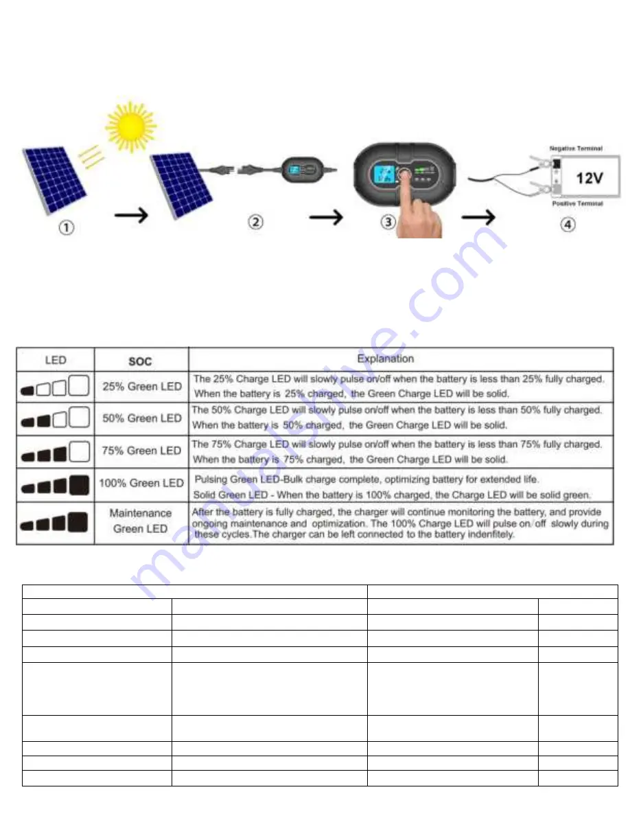
4.1 Connecting to Solar Panel and Battery.
Do not connect the charge controller until all other connections are made. Identify the correct polarity of the solar panel
and battery terminals. The male SAE connector is positive and female SAE connector is negative, the positive battery
terminal is typically marked by these letters or symbol (POS,P,+). The negative battery terminal is typically marked by
these letters or symbol (NEG,N,-). Do not make any connections to the carburetor, fuel lines, or thin, sheet metal parts.
1) Expose the solar panel to full sun without shade.
2) Connect solar panel to charge controller, the LED screen will illuminate and display PV charge voltage and no current.
3) Press the mode button to toggle to the appropriate battery types, the battery LED will illuminate the selected mode
4) Connect the charge controller to battery terminals, Wait 5-10s, the charge controller will enter charging mode once it
recognizes the battery. The SOC indicator will illuminate and LED screen will display the battery voltage and charge
current.
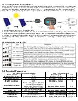
4.2 Understanding Charge LEDs.
5.0 Technical Parameters
10A Charge Controller Parameters
Solar Panel Parameters
Rated Current
10A
Power Output
20W
Nominal System Voltage
12V DC
Power Tolerance
±
5%
Max PV Input Voltage
15-30V
Open Circuit Voltage
21.6V
Max PV Input Power
120W
Short Circuit Current
1.17A
Electronics Protections
Reverse battery polarity, Reverse
PV polarity, PV over-voltage
Battery over-voltage, PV over-
current, Battery over-current
Maximum Power Voltage
18.0V
Battery Type
Wet Cell, Gel Cell, Flooded,
Maintenance-free, AGM, Lithium
Maximum Power Current
1.12A
Controller Terminals
1.5mm2/16AWG
Current Temp Coefficient
0.1 %/
°
C
Power Indicator
25%-50%-75%-100%
Voltage Temp Coefficient
-0.37 %/
°
C
Standby Current
0 mA(No discharge from battery)
Power Temp Coefficient
-0.45 %/
°
C


