background image

- 116 - 


A

NSCHLUSSBEREICH DER 

H

ILFSKONTAKTE


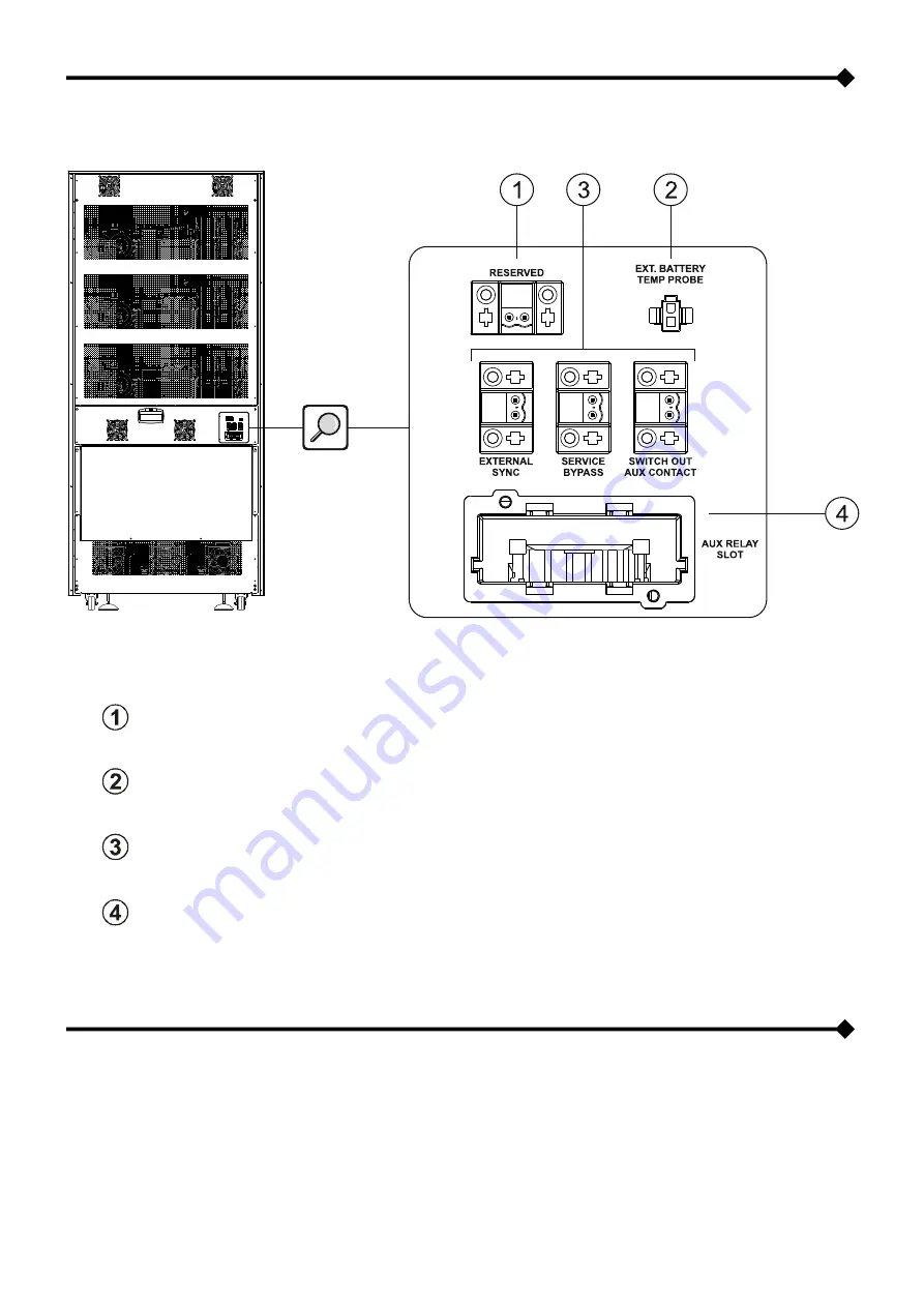
RESERVED

: Reserviertes Signal 


EXT. BATTERY TEMP PROBE

:


Anschluss für Temperatursensor für externe Batterien  


Von links nach rechts: 


EXTERNAL SYNC

: Anschluss für externes Synchronisierungssignal  


SERVICE BYPASS

: Anschluss für die Fernsteuerung des externen Wartungsbypasses  


SWITCH OUT AUX CONTACT

: Anschluss für Fernsteuerung externer Ausgangs-Trennschalter   


AUX RELAY SLOT

: Relais-Slot 


S

EPARATER 

B

YPASS

-E

INGANG


DIE USV-BAUREIHE KANN MIT DER OPTION "DUAL-INPUT" KONFIGURIERT WERDEN, D.H. DIE BYPASS-LEITUNG IST 
VON DER EINGANGSLEITUNG GETRENNT.  

 
In diesem Fall werden die Eingangsleitung und die Bypass-Leitung separat ausgeführt. 
Der  USV-Ausgang  wird mit der  Bypassleitung  synchronisiert,  so  dass eine  asynchrone Verbindung  bei  einem  automatischen 
Umschalten  auf  die  Bypass-Versorgung  oder  bei  einem  manuellen  Schließen  der  Bypass-Leitung  (SWMB),  zwischen 
Bypassleitung und Wechselrichterleitung verhindert wird. 


Summary of Contents for SEMIS T33

Page 1: ...BRECHUNGSFREIEN BETRIEB SEMIS T33 Online UPS Manuale d installazione ed uso Installation and use manual Installations und Bedienungsanleitung Manuel d installation et d utilisation Manual de instalac...

Page 2: ...mbientale sviluppato dall azienda in accordo con la normativa vigente In questo prodotto non sono presenti materiali pericolosi come CFC HCFC o amianto L imballo costituito da MATERIALE RICICLABILE Sm...

Page 3: ...BIO ARIA PER LOCALE BATTERIA 15 RIMOZIONE DELL UPS DAL PALLET 16 CONTROLLO DEL CONTENUTO DELLA SCATOLA ACCESSORI 18 POSIZIONAMENTO DELL UPS 18 COLLEGAMENTI ELETTRICI 19 DIMENSIONAMENTO DEI CAVI DI COL...

Page 4: ...VENTOLE 33 DISPLAY GRAFICO 34 MENU DISPLAY 36 MODALIT DI FUNZIONAMENTO 37 BYPASS MANUALE SWMB 37 ALIMENTATORE AUSILIARIO RIDONDANTE PER BYPASS AUTOMATICO 38 POWER WALK IN 38 DECLASSAMENTO DELLA POTENZ...

Page 5: ...ma generazione hanno permesso di raggiungere elevate prestazioni quali ZERO IMPACT SOURCE garantisce bassa distorsione d ingresso fattore di potenza prossimo a uno e massima compatibilit con il gruppo...

Page 6: ...7 VISTE ANTERIORI UPS Pannello di controllo con display grafico Piedi di stazionamento dell UPS Griglie di aerazione Ruote per la movimentazione dell UPS Porta frontale con serratura...

Page 7: ...accia utente Da sinistra a destra Sezionatore di ingresso SWIN Sezionatore di ingresso bypass SWBYP Sezionatore di bypass manuale SWMB Sezionatore di uscita SWOUT Ventole moduli potenza Ventole bypass...

Page 8: ...istra a destra Connettore Remote Emergency Power Off R E P O Porta contatti AS400 Porta comunicazione USB Porta comunicazione RS232 Pulsante partenza da batteria COLD START Slot per schede accessorie...

Page 9: ...10 VISTA POSTERIORE UPS Ventole controllo Accesso collegamenti IN OUT Accesso contatti ausiliari Ventole bypass secondarie Ventole caricabatterie...

Page 10: ...settiera dell UPS BATTERY N Connessioni di potenza E NEUTRO DI BATTERIA INPUT L1 L2 L3 N Connessioni di potenza FASI E NEUTRO DI INGRESSO BYPASS L1B L2B L3B Connessioni di potenza FASI BYPASS SEPARATO...

Page 11: ...per ausiliario sezionatore d uscita remoto AUX RELAY SLOT Slot Rel INGRESSO BYPASS SEPARATO QUESTA SERIE DI UPS PU ESSERE CONFIGURATA IN MODALIT DUAL INPUT OSSIA CON LINEA DI BYPASS SEPARATA DA QUELLA...

Page 12: ...nzionamento da batteria con preallarme di fine scarica o shutdown imminente Lampeggiante in Stand by funzione di riaccensione programmata attiva e rete assente LED carico su bypass Acceso fisso carico...

Page 13: ...r maggiori informazioni fare riferimento al manuale Installation Instructions fornito in dotazione evitare gli ambienti polverosi verificare che il pavimento sia in piano e in grado di sostenere il pe...

Page 14: ...azione di idrogeno emesso durante la carica dalle batterie al di sotto del limite di pericolo L aria di ricambio del locale deve essere assicurata preferibilmente per ventilazione naturale nel caso in...

Page 15: ...di chiusura posti ai lati dell imballo Aprirli sollevandoli come mostrato in figura Sollevare il coperchio ed aprire la scatola di cartone Rimuovere il contenitore accessori NOTA la scatola accessori...

Page 16: ...nto delle forche ATTENZIONE Ogni qual volta ci sia la necessit di sollevare l UPS prima di procedere si raccomanda sempre di posizionare le forche solamente nei punti indicati dalle apposite etichette...

Page 17: ...ca e la porta non sono idonee a fungere come punti di spinta o di appiglio davanti e dietro all apparecchiatura si dovr garantire almeno lo spazio libero sufficiente per consentire le operazioni di av...

Page 18: ...effettuare quella del conduttore di protezione cavo di terra da collegare alla vite siglata PE L UPS deve funzionare con il collegamento all impianto di terra Il Neutro d ingresso deve essere sempre c...

Page 19: ...UPS collegare il conduttore di protezione cavo di terra alla barra per le connessioni di potenza a terra siglata PE collegare i cavi d ingresso di bypass d uscita e di batteria alla morsettiera rispet...

Page 20: ...21 SCHEMI DI CONNESSIONE ALL IMPIANTO ELETTRICO UPS senza variazione di regime di neutro UPS con isolamento galvanico in ingresso UPS con isolamento galvanico in uscita...

Page 21: ...enza variazione di regime di neutro e con ingresso bypass separato UPS con isolamento galvanico in ingresso e con ingresso bypass separato UPS con isolamento galvanico in uscita e con ingresso bypass...

Page 22: ...ovranno essere riferiti allo stesso potenziale Qualora le due alimentazioni fossero differenti necessario utilizzare un trasformatore di isolamento su uno degli ingressi UPS senza variazione di regime...

Page 23: ...ico su bypass Se il guasto si verifica con UPS in funzionamento da batteria il carico rimane non alimentato Volendo evitare lo spegnimento dell inverter e mantenere quindi il carico alimentato da inve...

Page 24: ...ferenziale a monte del punto in cui la linea si divide per alimentare gli ingressi raddrizzatore e by pass del UPS protetti da interruttore magnetotermico Vedi figura seguente Versioni PARALLELO Per e...

Page 25: ...edi Sezione contatti ausiliari sono disponibili i morsetti per collegare i contatti ausiliari dei sezionatori bypass di manutenzione remoto e uscita remoto Questi sono identificati rispettivamente dal...

Page 26: ...dal costruttore eventuali utilizzi non conformi a quanto specificato possono causare malfunzionamenti o rotture all apparecchiatura Per l eventuale installazione collegare il cavo contenuto nell appo...

Page 27: ...S Utilizzare cavo doppio isolamento di sezione 1mmq per il collegamento dei morsetti SERVICE BYPASS e AUX SWOUT ai relativi contatti ausiliari dei sezionatori BYPASS DI MANUTENZIONE REMOTO 3 e USCITA...

Page 28: ...PS Nel caso di UPS connessi in parallelo non sono disponibili le modalit di funzionamento ECO LINE INTERACTIVE SMART SMART ACTIVE e STBYOFF STAND BY OFF Per il collegamento in parallelo degli UPS nece...

Page 29: ...ppresentato lo schema a blocchi dell UPS e vengono descritte le singole parti che lo compongono Diagramma a blocchi dell UPS IMPORTANTE I nostri gruppi di continuit sono concepiti e realizzati per una...

Page 30: ...tteria esterna all UPS Dopo aver verificato la corretta polarit delle connessioni chiudere il sezionatore fusibili della linea di batteria esterna all UPS ATTENZIONE se stato effettuato un collegament...

Page 31: ...ONE necessario configurare l UPS per settare i valori corretti della capacit nominale complessiva di batteria Tale operazione deve essere effettuata tramite il software di configurazione dedicato e ri...

Page 32: ...e nuovamente il pulsante per confermare Si accendono tutti i led attorno al display per 1 sec circa ed il buzzer inizia ad emettere un beep ogni 7 sec La sequenza di accensione termina quando l UPS si...

Page 33: ...Battery Line Inverter Load Inverter Output Line Battery Charge Automatic Static Bypass Lo schema mostra lo stato dei tre moduli logici di potenza PFC Converter Inverter Automatic Static Bypass Ogni m...

Page 34: ...TI Zona di visualizzazione dello stato di funzionamento dell UPS La prima riga sempre attiva e visualizza costantemente lo stato dell UPS in quell istante La seconda si attiva solo in presenza di un e...

Page 35: ...36 MENU DISPLAY...

Page 36: ...nominale ed il bypass non pi utilizzabile free running mode ATTENZIONE Nel caso di UPS connessi in parallelo non sono disponibili le modalit di funzionamento ECO LINE INTERACTIVE SMART SMART ACTIVE e...

Page 37: ...ER WALK IN L UPS dotato di serie della modalit Power Walk In attivabile e configurabile tramite il software di configurazione Quando la modalit attiva al ritorno rete dopo un periodo in autonomia l UP...

Page 38: ...t 2 sec viene reimpostata automaticamente la lingua inglese La modifica della funzione pu essere bloccata tramite il software di configurazione Nella seguente tabella sono elencate le configurazioni...

Page 39: ...zionamento in modalit ECO Normal Eco mode min max threshold Range di tensione ammesso per il funzionamento in modalit ECO Low 200V High 253V UPS without battery Modalit di funzionamento senza batterie...

Page 40: ...NNETTORE RS232 CONNETTORE USB PIN NOME TIPO SEGNALE PIN SEGNALE 1 IN 1 VBUS 2 TX OUT TX linea seriale 2 D 3 RX IN RX linea seriale 3 D 4 4 GND 5 GND POWER 6 OUT 7 8 15V POWER Alimentazione isolata 15V...

Page 41: ...riprende a funzionare da inverter Se il ponticello viene rimosso in mancanza di rete l UPS riprende il funzionamento da batteria 4 5 12 BATTERY LOW OUTPUT 1 Segnala che le batterie sono a fine scarica...

Page 42: ...inserimento di un carico distorcente Suono C La segnalazione viene fatta quando l UPS passa in funzionamento da batteria prima della segnalazione di fine scarica suono D possibile tacitare la segnala...

Page 43: ...operativo desiderato Collegare la porta di comunicazione RS232 dell UPS ad una porta di comunicazione COM del PC tramite il cavo seriale in dotazione oppure collegare la porta USB dell UPS ad una por...

Page 44: ...IETRO LA PORTA SWIN APERTO Chiudere il sezionatore MANCANZA DELLA TENSIONE DI RETE BLACKOUT Verificare la presenza della tensione di rete elettrica Eventualmente eseguire l accensione da batteria per...

Page 45: ...NZIONAMENTO NELLO STADIO DI INGRESSO DELL UPS Azionare il bypass manuale SWMB spegnere e poi riaccendere l UPS Escludere il bypass manuale Se il problema permane contattare il centro assistenza pi vic...

Page 46: ...e l accensione andando nel men ACCENSIONE IL DISPLAY VISUALIZZA UNO O PI DEI SEGUENTI CODICI F06 F07 F08 SEZIONAMENTO D INGRESSO IN CORTOCIRCUITO Azionare il bypass manuale SWMB spegnere l UPS aprire...

Page 47: ...DI CALORE IN PROSSIMIT DELL UPS FERITOIE DI AERAZIONE OSTRUITE O TROPPO VICINE ALLE PARETI MALFUNZIONAMENTO DEL SENSORE DI TEMPERATURA O DEL SISTEMA DI RAFFREDDAMENTO DEL CARICABATTERIE Rimuovere la...

Page 48: ...alimentato S11 UPS in blocco carico su bypass S12 Stadio BOOST o caricabatterie in blocco carico non alimentato S13 Convertitore di frequenza carico alimentato da inverter COMMAND indica la presenza...

Page 49: ...del bypass fuori tolleranza A18 Tensione su linea bypass fuori tolleranza A22 Carico su Fase1 della soglia utente impostata A23 Carico su Fase2 della soglia utente impostata A24 Carico su Fase3 della...

Page 50: ...er deformata F16 Sinusoide Fase3 inverter deformata F17 Anomalia stadio Inverter F19 Sovratensione batterie positive F20 Sovratensione batterie negative F23 Sovraccarico in uscita F26 Teleruttore d us...

Page 51: ...L16 Sovratensione inverter Fase3 L17 Sottotensione inverter Fase1 L18 Sottotensione inverter Fase2 L19 Sottotensione inverter Fase3 L20 Tensione continua in uscita inverter o Sinusoide inverter deform...

Page 52: ...Trifase con neutro 4wire Frequenza Nominale 5 50 60Hz Corrente nominale di uscita 232A 290A Potenza apparente nominale in uscita 160kVA 200kVA Potenza attiva nominale in uscita 160kW 200kW Fattore di...

Page 53: ...carico nominale PF 1 batterie a tensione nominale 3 100 load THDv 1 4 Per mantenere la tensione di uscita entro il campo di precisione indicato pu rendersi necessaria una ricalibrazione dopo un lungo...

Page 54: ...eveloped by the company in compliance with applicable standards Hazardous materials such as CFCs HCFCs or asbestos have not been used in this product Packaging is composed of RECYCLABLE MATERIALS Disp...

Page 55: ...R EXCHANGE IN THE BATTERY ROOM 67 REMOVING THE UPS FROM THE PALLET 68 CHECKING THE CONTENTS OF THE ACCESSORIES BOX 70 UPS POSITIONING 70 ELECTRICAL CONNECTIONS 71 CABLE SIZES 71 PRELIMINARY OPERATIONS...

Page 56: ...UTDOWN 85 FAN MANAGEMENT 85 GRAPHIC DISPLAY 86 DISPLAY MENU 88 OPERATING MODE 89 MANUAL BYPASS SWMB 89 REDUNDANT AUXILIARY POWER ADAPTER FOR AUTOMATIC BYPASS 90 POWER WALK IN 90 DERATING OF POWER FOR...

Page 57: ...e components provide superior performance Here are some examples ZERO IMPACT SOURCE ensures low input distortion power factor close to one and maximum compatibility with the generator BATTERY CARE SYS...

Page 58: ...59 FRONT UPS VIEWS Control panel with graphic display UPS feet Ventilation grille Wheels for UPS handling Front door with lock...

Page 59: ...60 User interface Left to right SWOUT Output switch SWBYP Bypass input switch SWMB manual bypass switch SWOUT Output switch Power module fans Primary bypass fans...

Page 60: ...Left to right R E P O Remote Emergency Power Off connector AS400 Contacts port USB communication port RS232 communication port COLD START battery start up button Slot for accessory communications car...

Page 61: ...62 UPS REAR VIEW Control fans IN OUT connection access Auxiliary contact access Secondary bypass fans Battery charger fans...

Page 62: ...terminal board BATTERY N Power connections BATTERY and NEUTRAL INPUT L1 L2 L3 N Power connections INPUT PHASES AND NEUTRAL BYPASS L1B L2B L3B Power connections SEPARATE BYPASS PHASES OUTPUT L1 L2 L3...

Page 63: ...for remote auxiliary output switch AUX RELAY SLOT Relay slot SEPARATE BYPASS INPUT THIS SERIES OF UPS UNITS CAN BE CONFIGURED IN DUAL INPUT MODE I E WITH THE BYPASS LINE SEPARATE FROM THE INPUT LINE...

Page 64: ...g battery operation with early low battery or imminent shutdown warning Flashing in standby programmed restart function active and mains absent Load on bypass LED Steady on load powered from bypass li...

Page 65: ...dusty environments ensure that flooring is flat and able to sustain the weight of the UPS and Battery Boxes avoid environments that are too narrow which might prevent normal maintenance operations rel...

Page 66: ...enerated during charging within safe limits The room should preferably be ventilated naturally if it cannot be forced ventilation may be employed Standard EN 50272 2 regarding air exchange provides th...

Page 67: ...Find the 4 hooks at the sides of the package lift them to open as shown in the figure Lift the lid and open the carton Remove the accessories container NOTE the accessories box may be located inside t...

Page 68: ...lift truck take care to position the forks properly CAUTION Whenever you need to lift the UPS make sure that the forks are always positioned as indicated by the labels shown in the figure NOTE retain...

Page 69: ...sitioning so for short trips plastic parts and the door are not able to act as pushing points or handles leave sufficient clearance in front of and behind the device to allow for startup shutdown and...

Page 70: ...ve conductor earth wire to be connected to the screw marked PE The UPS must operate while connected to the earthing system The input Neutral must always be connected CAUTION a three phase 4 wire distr...

Page 71: ...PS rear views hook up the GND cable to the power connection bar marked PE connect the input bypass output and battery cables to the terminal board following the positions and polarities indicated in U...

Page 72: ...73 ELECTRICAL SYSTEM CONNECTION DIAGRAMS UPS without neutral connectivity variation UPS with galvanic input insulation UPS with galvanic output insulation...

Page 73: ...PS without neutral connectivity variation and with separate bypass input UPS with galvanic input insulation and with separate bypass input UPS with galvanic output insulation and with separate bypass...

Page 74: ...ore they will have to be connected to the same potential If the two power supplies are different you must use an isolation transformer on one of the inputs UPS without neutral connectivity variation a...

Page 75: ...pass line the protection switches off the inverter and switches the load to the bypass If the fault occurs with the UPS in battery operation the load remains unpowered To prevent the inverter switchin...

Page 76: ...l switch must be fitted upstream of the point at which the line divides to supply the trip switch protected rectifier and bypass inputs for the UPS See following diagram PARALLEL versions In order to...

Page 77: ...nd remote output bypass switches are available at the back of the UPS see Auxiliary contacts section These are identified respectively by the words SERVICE BYPASS and AUX SWOUT For installation refer...

Page 78: ...ONLY the kit provided by the manufacturer use which does not observe the specifications may cause the equipment to malfunction or fail For installation connect the cable contained in the special kit t...

Page 79: ...S currents Use a double insulation cable with a 1mm2 section for connecting SERVICE BYPASS and AUX SWOUT terminals to relative REMOTE MAINTENANCE BYPASS 3 and OUTPUT 2 switch auxiliary contacts Verify...

Page 80: ...hen UPS s are connected in parallel the ECO LINE INTERACTIVE SMART SMART ACTIVE and STBYOFF STAND BY OFF modes are not available The optional parallel connection kit is required to connect multiple UP...

Page 81: ...he following is a block diagram of the UPS which describes the individual components that it is composed of UPS block diagram IMPORTANT Our UPS have been designed and built for long term duration even...

Page 82: ...external battery line switch fuse Check the polarity of the connections then close the external battery line switch fuses CAUTION any connection not compliant with the Installation Instructions may d...

Page 83: ...battery capacity CAUTION you must configure the UPS to set the correct total nominal battery capacity This operation must be performed by means of the configuration software reserved for Service perso...

Page 84: ...ct YES and press again to confirm The leds around the display turn on for 1 second and the buzzer will start beeping every 7 seconds The start sequence is completed when the UPS is set to battery oper...

Page 85: ...verter Output Line Battery Charge Automatic Static Bypass The diagram shows the status of the three power logical modules PFC Converter Inverter Automatic Static Bypass Each module can take on one of...

Page 86: ...TATUS ERRORS FAULTS UPS operation status display area The first row is always active and constantly displays UPS status in real time The second is activated only in the presence of a UPS error and or...

Page 87: ...88 DISPLAY MENU...

Page 88: ...e of this tolerance the UPS desynchronizes bringing itself to the nominal frequency and bypass can no longer be used free running mode CAUTION When UPS s are connected in parallel the ECO LINE INTERAC...

Page 89: ...ch can be activated and configured via configuration software When this mode is enabled once the mains power is restored after a period of autonomy the UPS begins absorbing from it again progressively...

Page 90: ...sly for t 2 sec and English will automatically be reset Function modification can be locked out with the configuration software Configurations which can be modified by means of configuration software...

Page 91: ...Low 180V High 264V Eco mode sensibility Selects the intervention sensitivity during operation in ECO mode Normal Eco mode min max threshold Selects the accepted voltage range for operation in ECO mode...

Page 92: ...S RS232 CONNECTOR USB CONNECTOR PIN NAME TYPE SIGNALS PIN SIGNALS 1 IN 1 VBUS 2 TX OUT TX serial line 2 D 3 RX IN RX serial line 3 D 4 4 GND 5 GND POWER 6 OUT 7 8 15V POWER Isolated power 15V 5 80mA m...

Page 93: ...e of power the UPS will begin operation via the inverter If the jumper is removed without power the UPS will begin operation via batteries 4 5 12 BATTERY LOW OUTPUT 1 Signals that batteries are low wh...

Page 94: ...rges due to the insertion of a distorted current Sound C This signal is emitted when the UPS switches to battery operation before No Battery is signalled sound D It is possible to silence signals see...

Page 95: ...com selecting the desired operating system Connect the UPS RS232 communication port to a PC COM communication port by means of the supplied serial cable or connect the UPS USB port to a PC USB port v...

Page 96: ...indicated in the Installation paragraph THE SWITCH BEHIND THE DOOR SWIN IS OPEN Close the switch NO MAINS VOLTAGE BLACKOUT Verify electrical main voltage presence If necessary switch on via batteries...

Page 97: ...MORE OF THE FOLLOWING CODES F09 F10 UPS INPUT STAGE MALFUNCTION Activate manual bypass SWMB switch off and re start the UPS Exclude manual bypass Contact the nearest service centre if this problem pe...

Page 98: ...ON menu THE DISPLAY SHOWS ONE OR MORE OF THE FOLLOWING CODES F06 F07 F08 INPUT SWITCH SHORTCIRCUITED Operate the manual bypass SWMB switch the UPS off open SWIN and contact your local service centre c...

Page 99: ...UPS VENTILATION SLITS OBSTRUCTED OR TOO CLOSE TO WALLS TEMPERATURE SENSOR OR BATTERY CHARGER COOLING SYSTEM MALFUNCTION Remove the cause of over temperature Insert manual bypass SWMB without switchin...

Page 100: ...rt up S10 UPS locked load not powered S11 UPS locked load on bypass S12 BOOST stage or battery charger locked load not powered S13 Frequency converter load powered by inverter COMMAND indicates presen...

Page 101: ...nce range A16 Bypass frequency out of tolerance range A18 Voltage on bypass line out of tolerance range A22 Load on Phase1 set user threshold A23 Load on Phase2 set user threshold A24 Load on Phase3 s...

Page 102: ...e2 sinusoid inverter deformed F16 Phase3 sinusoid inverter deformed F17 Inverter stage fault F19 Positive battery overvoltage F20 Negative battery overvoltage F23 Output overload F26 Phase1 output swi...

Page 103: ...3 inverter overvoltage L17 Phase1 inverter undervoltage L18 Phase2 inverter undervoltage L19 Phase3 inverter undervoltage L20 Continuous voltage on inverter output or Phase1 sinusoid inverter deformed...

Page 104: ...00 415 V AC three phase with neutral 4 wire Nominal frequency 5 50 60Hz Output nominal current 232A 290A Apparent nominal output power 160kVA 200kVA Active nominal output power 160kW 200kW Output powe...

Page 105: ...ing conditions nominal load PF 1 battery at nominal voltage 3 100 load THDv 1 4 To keep the output voltage within the specified precision you may need to recalibrate the unit after it has been in serv...

Page 106: ...mweltmanagementsystems zugrunde die vom Hersteller in bereinstimmung mit den geltenden Gesetzesvorschriften festgelegt wurden Gefahrenstoffe wie CFC HCFC oder Asbest sind nicht enthalten Die Verpackun...

Page 107: ...UFUHR IM BATTERIERAUM 119 USV VON DER TRANSPORTPALETTE ABLADEN 120 INHALTSKONTROLLE DER ZUBEH RPACKUNG 122 USV AUFSTELLEN 122 STROMANSCHL SSE 123 DIMENSIONIERUNG DER LEISTUNGSVERKABELUNG 123 VORABMA N...

Page 108: ...EN 137 GEBL SESTEUERUNG 137 GRAPHISCHES DISPLAY 138 DISPLAYMEN S 140 BETRIEBSMODUS 141 MANUELLER BYPASS SWMB 141 REDUNDANTES NETZTEIL F R AUTOMATISCHEN BYPASS 142 POWER WALK IN 142 LEISTUNGSDROSSELUNG...

Page 109: ...ie z B ZERO IMPACT SOURCE Gew hrleistet u erst geringe Verzerrungen des Eingangsstroms einen Leistungsfaktor von 0 99 und maximale Kompatibilit t mit Netzersatzaggregaten BATTERY CARE SYSTEM Erm glich...

Page 110: ...111 VORDERANSICHTEN DER USV Bedienfeld mit graphischem Display Standf e der USV Bel ftungsgitter Transportr der der USV Frontt r mit Verschluss...

Page 111: ...utzeroberfl che Von links nach rechts Eingangstrennschalter SWIN Bypass Eingangstrennschalter SWBYP Manueller Bypass Trennschalter SWMB Ausgangstrennschalter SWOUT Leistungs Gebl semodule Haupt Bypass...

Page 112: ...links nach rechts Anschluss Remote Emergency Power Off R E P O AS400 Kontaktschnittstelle USB Kommunikationsschnittstelle RS232 Kommunikationsschnittstelle Batterie Startschalter COLD START Steckplat...

Page 113: ...114 R CKANSICHT DER USV Gebl se der Steuereinheiten Anschlusszug nge IN OUT Zug nge zu Hilfskontakten Neben Bypassgebl se K hlventilator des Batterieladeger ts...

Page 114: ...USV Klemmleiste BATTERY N Leistungsanschl sse UND BATTERIE NEUTRALLEITER INPUT L1 L2 L3 N Leistungsanschl sse PHASEN UND EINGANGS NEUTRALLEITER BYPASS L1B L2B L3B Leistungsanschl sse GETRENNTE BYPASS...

Page 115: ...Ausgangs Trennschalter AUX RELAY SLOT Relais Slot SEPARATER BYPASS EINGANG DIE USV BAUREIHE KANN MIT DER OPTION DUAL INPUT KONFIGURIERT WERDEN D H DIE BYPASS LEITUNG IST VON DER EINGANGSLEITUNG GETREN...

Page 116: ...nkt Batteriebetrieb mit Voralarm Autonomiezeitende Batterie fast entladen Ausschalten steht bevor Blinkt im Stand by Programmierte Einschaltfunktion aktiv Netzversorgung nicht vorhanden LED Last auf B...

Page 117: ...onen siehe mitgeliefertes Benutzerhandbuch Installation Instructions Staubige Orte vermeiden Sicherstellen dass der Boden ebenerdig ist und das Gewicht der USV und der Batterieanlage tragen kann Beson...

Page 118: ...on des Wasserstoffs der sich beim Laden der Batterien bildet unterhalb der Gefahrenschwelle zu halten Der Luftaustausch im Raum sollte m glichst durch Eigenl ftung sichergestellt werden Ist dies nicht...

Page 119: ...haken seitlich der Verpackung ermitteln diese durch Anheben wie in der Abbildung angezeigt ffnen Die Abdeckung abnehmen und den Karton ffnen Das Zubeh r entnehmen HINWEIS Das Zubeh r ist in der Verpac...

Page 120: ...ltr ger achten ACHTUNG Immer wenn das Anheben der USV notwendig ist sollten die Gabeltr ger vorher stets an den mittels entsprechender Klebeetiketten angezeigten Punkten wie in der Abbildung angezeigt...

Page 121: ...d T r sind nicht als Halte oder Schubvorrichtungen geeignet Vor dem Ger t stets ausreichend Freiraum zur Bedienung des Ger ts Ein und Ausschalten und f r Wartungsma nahmen lassen Auf der Oberseite kei...

Page 122: ...eiter Erdungsleitung an die mit PE gekennzeichnete Schraube angeschlossen werden Die USV muss mit dem Anschluss an die Erdungsanlage betrieben werden Der Eingangs Neutralleiter muss stets eine Netzver...

Page 123: ...kansichten USV den Schutzleiter Erdungskabel an die mit PE gekennzeichnete Leiste f r die geerdeten Leistungsanschl sse anschlie en Eingangs Bypass Ausgangs und Batteriekabel an der Klemmleiste anschl...

Page 124: ...125 BEISPIELE F R DEN ANSCHLUSS AN DAS STROMNETZ USV ohne nderung des Neutralleiters USV mit galvanisch isoliertem Eingang USV mit galvanisch isoliertem Ausgang...

Page 125: ...ohne nderung des Neutralleiters und mit separatem Bypass Eingang USV mit galvanisch isoliertem Eingang und mit separatem Bypass Eingang USV mit galvanisch isoliertem Ausgang und mit separatem Bypass...

Page 126: ...rt und m ssen somit dasselbe Potential aufweisen Bei unterschiedlichen Eingangspotentialen muss an einem der beiden Eing nge ein Isolationstransformator verwendet werden USV ohne nderung des Neutralle...

Page 127: ...leitet die Last auf den Bypass um Wenn die St rung bei der USV im Batteriebetrieb auftritt wird die Last nicht mehr gespeist Um das Ausschalten des Wechselrichters zu vermeiden und die Last durch den...

Page 128: ...ltet sein an dem sich die Leitung teilt um die durch einen Leitungsschutzschalter gesch tzten Gleichrichter und Bypass Eing nge der USV Einheit zu versorgen Siehe folgende Abbildung PARALLELANSCHLUSS...

Page 129: ...fskontakte f r die Fernsteuerung der Wartungsbypass und Ausgangs Trennschalter vorhanden Diese sind als SERVICE BYPASS und AUX SWOUT entsprechend gekennzeichnet Zur Installation siehe Querschnitt der...

Page 130: ...ich der beim Hersteller erh ltliche spezielle Bausatz verwendet werden Jeder nicht mit den hier aufgef hrten Angaben und Hinweisen konforme Gebrauch kann zu Betriebsst rungen und Defekten des Ger ts f...

Page 131: ...entsprechen Ein doppelt isoliertes Kabel mit 1 mm Querschnitt zur Verbindung der Klemmen SERVICE BYPASS AUX SWOUT und am Hilfskontakt des FERNGESTEUERTEN WARTUNGSBYPASSES 3 und des REMOTEAUSGANGSSCHA...

Page 132: ...s die USV parallelgeschaltet sind sind die Betriebsarten ECO LINE INTERACTIVE SMART SMART ACTIVE und STBYOFF STAND BY OFF nicht verf gbar F r die Parallelschaltung der USVs wird das Parallelset option...

Page 133: ...rne Temperatur sowie die Batterieanlage Es folgen eine Darstellung des Blockschemas der USV sowie eine Beschreibung der einzelnen Bestandteile Blockschema der USV WICHTIG Die unterbrechungsfreien Stro...

Page 134: ...V Korrekte Polung der Anschl sse berpr fen dann die Trennschalter Sicherungen der externen Batterieleitung zur USV schlie en ACHTUNG Bei Nicht bereinstimmung mit den Angaben aus dem Benutzerhandbuch I...

Page 135: ...Die USV muss konfiguriert werden um die korrekten Werte der gesamten Nennleistung der Batterie einzustellen Dieser Vorgang erfolgt ber die Konfigurationssoftware und kann nur vom Servicepersonal durc...

Page 136: ...und erneut mit best tigen Alle LEDs am Display leuchten etwa 1 Sekunde lang auf alle 7 Sekunden wird Signalton wird abgegeben Der Einschaltvorgang ist beendet sobald die USV auf Batteriebetrieb schalt...

Page 137: ...Line Ausgangsleitung des Wechselrichters Battery Charge Batterieladung Automatic Static Bypass Automatischer statischer Bypass Das Schema zeigt die drei Leistungsmodule PFC Converter Gleichrichter In...

Page 138: ...STATUS FEHLER ST RUNGEN Bereich in dem der Betriebsstatus der USV angezeigt wird Die erste Zeile ist immer aktiviert und zeigt durchgehend den aktuellen Betriebsstatus der USV an Die zweite Zeile ersc...

Page 139: ...140 DISPLAYMEN S...

Page 140: ...d die USV nicht synchronisiert sie schaltet auf Nennfrequenz und der Bypass kann nicht mehr genutzt werden free running mode ACHTUNG Falls die USV parallelgeschaltet sind sind die Betriebsarten ECO LI...

Page 141: ...dus ausgestattet der ber die Konfigurationssoftware aktiviert und konfiguriert wird Ist dieser Modus aktiviert so erfolgt bei der R ckkehr der Netzversorgung nach einem Batteriebetrieb die Leistungsau...

Page 142: ...t Durch gleichzeitiges Dr cken der Tasten F1 und F4 mehr als 2 Sekunden schaltet die Spracheinstellung automatisch auf Englisch Die Bearbeitung dieser Funktion kann mit der Konfigurationssoftware gesp...

Page 143: ...erten Spannungsbereiches f r Umschaltung auf Bypass Low 180V High 264V Eco mode sensibility Auswahl der Eingriffssensibilit t w hrend des ECO Betriebs Normal Eco mode min max threshold Auswahl des Spa...

Page 144: ...ECKER USB STECKER PIN NAME TYP SIGNAL PIN SIGNAL 1 IN 1 VBUS 2 TX OUT TX serielle Schnittstelle 2 D 3 RX IN RX serielle Schnittstelle 3 D 4 4 GND 5 GND POWER 6 OUT 7 8 15V POWER Isolierte Versorgung 1...

Page 145: ...den Wechselrichterbetrieb wieder auf Wird die berbr ckung bei Netzausfall aufgehoben nimmt die USV den Batteriebetrieb wieder auf 4 5 12 BATTERY LOW OUTPUT 1 Zeigt eine geringe Batteriekapazit t an we...

Page 146: ...Ton C Dieser Signalton ert nt wenn die USV in den Batteriebetrieb wechselt noch bevor eine geringe Batteriekapazit t angezeigt wurde Ton D Der Signalton kann abgestellt werden siehe Abschnitt Graphisc...

Page 147: ...das gew nschte Betriebssystem angeben Die RS232 Schnittstelle der USV an eine Kommunikationsschnittstelle COM des PCs mit dem im Lieferumfang enthaltenen seriellen Kabel anschlie en oder den USB Ansc...

Page 148: ...t Installation beschrieben ausf hren TRENNSCHALTER HINTER DER FRONTT R SWIN GE FFNET Trennschalter schlie en FEHLEN VON NETZSPANNUNG STROMAUSFALL Spannungsversorgung des Stromnetzes berpr fen Zur Vers...

Page 149: ...GT F09 F10 ST RUNG DES EINGANGS STATUS DER USV Manuellen Bypass SWMB bet tigen USV aus und dann wieder einschalten Manuellen Bypass ausschalten Bei anhaltender St rung bitte mit dem Kundendienst Konta...

Page 150: ...rten oder vom Men aus das Einschalten der Batterieladung manuell im Men unter EINSCHALTEN starten AUF DEM DISPLAY WIRD EINER ODER MEHRERE DER FOLGENDEN CODES ANGEZEIGT F06 F07 F08 EINGANGSTRENNSCHALTU...

Page 151: ...R WAND ZU GERING ST RUNG DES TEMPERATURSENSORS ODER DER K HLUNG DES BATTERIELADEGER TS Ursache der berhitzung beheben Manuellen Bypass SWMB einschalten ohne die USV auszuschalten und abwarten bis die...

Page 152: ...ung ber Bypass S12 BOOST oder Batterieladeger t blockiert Keine Lastversorgung S13 Frequenzwandler Lastversorgung ber Wechselrichter COMMAND Weist auf eine aktive Fernsteuerung hin CODE BESCHREIBUNG C...

Page 153: ...Leitung Phase 3 Grenzwert berschritten A16 Bypass Frequenz Grenzwert berschritten A18 Spannung in Bypass Leitung Grenzwert berschritten A22 Last an Phase 1 der eingestellte Grenzwert A23 Last an Phase...

Page 154: ...hase 2 Wechselrichter F16 Sinusverformung Phase 3 Wechselrichter F17 Betriebsst rung Wechselrichter F19 berspannung Plusbatterien F20 berspannung Minusbatterien F23 berlast am Ausgang F26 Ausgangs Fer...

Page 155: ...nnung Wechselrichter Phase 3 L17 Unterspannung Wechselrichter Phase 1 L18 Unterspannung Wechselrichter Phase 2 L19 Unterspannung Wechselrichter Phase 3 L20 Dauerspannung am Wechselrichter Ausgang oder...

Page 156: ...0 415 Vac Dreiphasenspannung mit Neutralleiter 4 polig Nennfrequenz 5 50 60Hz Ausgangs Nennstrom 232A 290A Ausgangs Nennscheinleistung 160kVA 200kVA Ausgangs Nennwirkleistung 160kW 200kW Ausgangs Leis...

Page 157: ...nspannung 3 100 load THDv 1 4 Um die Ausgangsspannung im genannten Genauigkeitsbereich zu halten kann eine Neueichung nach einem langen Betriebszeitraum erforderlich werden 5 Bewegt sich die Netzfrequ...

Page 158: ...se conform ment la r glementation en vigueur Pour la construction de ce produit aucun mat riau dangereux tel que CFC HCFC ou amiante n a t utilis L emballage est con u en MATI RE RECYCLABLE Traiter to...

Page 159: ...71 EXTRACTION DE L UPS DE LA PALETTE 172 V RIFICATION DU CONTENU DE LA BO TE DES ACCESSOIRES 174 POSITIONNEMENT DE L UPS 174 BRANCHEMENTS LECTRIQUES 175 DIMENSIONNEMENT DES C BLES DE RACCORDEMENT 175...

Page 160: ...189 GESTION DES VENTILATEURS 189 CRAN GRAPHIQUE 190 MENUS L CRAN 192 MODE DE FONCTIONNEMENT 193 BY PASS MANUEL SWMB 193 ALIMENTATION AUXILIAIRE REDONDANTE POUR BY PASS AUTOMATIQUE 194 POWER WALK IN 19...

Page 161: ...que ZERO IMPACT SOURCE caract ristique qui permet de garantir un faible niveau de distorsion en entr e un facteur de puissance proche de 1 et une compatibilit maximale avec le groupe lectrog ne BATTER...

Page 162: ...163 VUES DE FACE DE L UPS Panneau de commande avec cran graphique Pieds de blocage de l UPS Grilles d a ration Roues de d placement de l UPS Porte frontale avec serrure...

Page 163: ...ateur De gauche droite Sectionneur d entr e SWIN Sectionneur d entr e by pass SWBYP Sectionneur de by pass manuel SWMB Sectionneur de sortie SWOUT Ventilateurs modules de puissance Ventilateurs face a...

Page 164: ...nt De gauche droite Connecteur Remote Emergency Power Off R E P O Port contacts AS400 Port communication USB Port communication RS232 Bouton de d marrage par batterie COLD START Slot pour cartes acces...

Page 165: ...166 VUE DE DOS UPS Ventilateurs commande Acc s raccordements IN OUT Acc s contacts auxiliaires Ventilateurs face arriere module by pass Ventilateurs chargeur de batterie...

Page 166: ...ornier de l UPS BATTERY N Connexions de puissance ET NEUTRE DE LA BATTERIE INPUT L1 L2 L3 N Connexions de puissance PHASES ET NEUTRE D ENTR E BYPASS L1B L2B L3B Connexions de puissance PHASES BY PASS...

Page 167: ...e sortie distance AUX RELAY SLOT Slot relais ENTREE DE BY PASS SEPARE CETTE S RIE D UPS PEUT TRE CONFIGUR E EN MODE DUAL INPUT C EST DIRE AVEC LA LIGNE DE BY PASS S PAR E DE LA LIGNE D ENTR E Dans ce...

Page 168: ...fonctionnement sur batterie avec pr alarme de fin de charge ou extinction shutdown imminente Clignotante en veille fonction de red marrage programm activ e et absence de r seau LED de charge sur by pa...

Page 169: ...lter le manuel Instructions d installation fourni avec l appareil viter les environnements poussi reux V rifier que le sol est parfaitement plat et capable de supporter le poids de l UPS et de la Batt...

Page 170: ...il faut pr voir une bonne circulation de l air dans le but de maintenir la concentration de l hydrog ne mis pendant la charge des batteries en dessous de la limite dite dangereuse Le renouvellement d...

Page 171: ...ure situ s sur les c t s de l emballage et les ouvrir en les soulevant tel que repr sent sur la figure Soulever le couvercle et ouvrir la bo te en carton Retirer la bo te contenant les accessoires REM...

Page 172: ...ENTION chaque fois qu il sera n cessaire de soulever l UPS avant de le faire il est recommand de toujours placer les fourches exclusivement aux points indiqu s sur les tiquettes pr vues cet effet comm...

Page 173: ...cements tr s brefs Les parties en plastique et la porte ne sont pas adapt es servir de zones de pouss e ou de prise Devant et derri re l quipement il faudra garantir un espace libre suffisant pour per...

Page 174: ...r est celle du conducteur de protection c ble de terre raccorder la vis portant la mention PE L UPS doit fonctionner en tant raccord e l installation de mise la terre Le Neutre d entr e doit toujours...

Page 175: ...raccorder le conducteur de protection c ble de terre la barre d di e aux connexions de puissance la terre portant la mention PE raccorder les c bles d entr e de by pass de sortie et de batterie au bor...

Page 176: ...177 SCHEMAS DE CONNEXION A L INSTALLATION ELECTRIQUE UPS sans changement de r gime de neutre UPS avec isolation galvanique en entr e UPS avec isolation galvanique en sortie...

Page 177: ...ans changement de r gime de neutre et avec entr e de by pass s par UPS avec isolation galvanique en entr e et avec entr e de by pass s par UPS avec isolation galvanique en sortie et avec entr e de by...

Page 178: ...ils devront se r f rer au m me potentiel Si les deux alimentations sont diff rentes il est n cessaire d utiliser un transformateur d isolement sur une des entr es UPS sans changement de r gime de neut...

Page 179: ...ors que l UPS fonctionne sur batterie la charge demeure non aliment e Si l on souhaite viter l extinction de l onduleur et maintenir ainsi la charge aliment e par l onduleur m me en cas de double pann...

Page 180: ...de la ligne pour alimenter les entr es du redresseur et du by pass de l UPS prot g es par un interrupteur thermomagn tique Voir figure suivante Versions PARALL LE Pour viter tout d clenchement erron...

Page 181: ...ntacts auxiliaires des bornes sont disponibles pour raccorder les contacts auxiliaires des sectionneurs de by pass d entretien distance et de sortie distance Elles sont respectivement identifi es par...

Page 182: ...uelles utilisations non conformes aux sp cifications peuvent causer des dysfonctionnements ou ruptures de l appareil Pour l installation ventuelle raccorder le c ble contenu dans le kit sp cial au con...

Page 183: ...double isolement de section de 1 mm2 pour le raccordement des bornes SERVICE BY PASS et AUX SWOUT aux contacts auxiliaires correspondants des sectionneurs de BY PASS D ENTRETIEN DISTANCE 3 et de SORT...

Page 184: ...UPS En cas d UPS connect s en parall le les modalit s de fonctionnement ECO LINE INTERACTIVE SMART SMART ACTIVE et STBYOFF STAND BY OFF ne sont pas disponibles Pour le raccordement en parall le des UP...

Page 185: ...si que la description des diff rentes parties qui le composent Sch ma fonctionnel de l UPS IMPORTANT Nos syst mes d alimentation sans coupure sont con us et r alis s pour une longue dur e m me dans le...

Page 186: ...l UPS Apr s avoir v rifi la polarit correcte des connexions fermer le sectionneur les fusibles de la ligne de batterie externe l UPS ATTENTION si un raccordement non conforme ce qui est report dans le...

Page 187: ...valeurs correctes de la capacit nominale globale de batterie Cette op ration doit tre effectu e l aide du logiciel de configuration d di et r serv au personnel de Service partir du menu principal appu...

Page 188: ...ur confirmer Toutes les LED autour de l cran s allument pendant 1 s environ et l avertisseur sonore commence mettre un bip toutes les 7 secondes La s quence d allumage se termine lorsque l UPS se met...

Page 189: ...er Onduleur Load Chargement Inverter Output Line Ligne de sortie onduleur Battery Charge Charge batterie Automatic Static Bypass By pass statique automatique Le sch ma montre l tat des trois modules l...

Page 190: ...d affichage de l tat de fonctionnement de l UPS La premi re ligne est toujours active et affiche constamment l tat de l UPS au moment de la consultation La seconde ligne s active uniquement en pr senc...

Page 191: ...192 MENUS A L ECRAN...

Page 192: ...e positionnant la fr quence nominale et le by pass n est plus utilisable free running mode ATTENTION En cas d UPS connect s en parall le les modalit s de fonctionnement ECO LINE INTERACTIVE SMART SMAR...

Page 193: ...ot e de s rie du mode Power Walk In qui peut tre activ et configur avec le logiciel de configuration Lorsque ce mode est actif au retour du courant apr s une p riode d autonomie l UPS continue de l ab...

Page 194: ...t 2 s la langue anglaise est automatiquement reconfigur e La modification de la fonction peut tre bloqu e l aide du logiciel de configuration Dans le tableau suivant se trouve la liste des configurati...

Page 195: ...ormal Eco mode sensibility S lection de la sensibilit en mode Eco Low 200V High 253V Eco mode min max threshold S lection de la tol rance de tension accept e pour le mode ECO Operating with Batteries...

Page 196: ...CONNECTEUR RS232 CONNECTEUR USB N BRO CHE NOM TYPE SIGNAL N BRO CHE SIGNAL 1 IN 1 VBUS 2 TX OUT TX ligne s rie 2 D 3 RX IN RX ligne s rie 3 D 4 4 GND 5 GND POWER 6 OUT 7 8 15V POWER Alimentation isol...

Page 197: ...a pr sence du courant l UPS reprend un fonctionnement par onduleur Si le pont est retir en l absence de courant l UPS reprend un fonctionnement sur batterie 4 5 12 BATTERY LOW OUTPUT 1 Signale que les...

Page 198: ...nt d l insertion d une charge de distorsion Son C Le signalement se pr sente lorsque l UPS passe en fonctionnement sur batterie avant le signalement de fin de charge son D Il est possible d teindre le...

Page 199: ...ctionnant le syst me d exploitation souhait Connecter le port de communication RS232 de l UPS un port de communication COM du PC avec le c ble s rie fourni avec le mat riel ou bien brancher le port US...

Page 200: ...SECTIONNEUR DERRI RE LE PORT SWIN EST OUVERT Fermer le sectionneur ABSENCE DE TENSION DE R SEAU BLACKOUT V rifier la pr sence de la tension de r seau lectrique ventuellement effectuer l allumage sur b...

Page 201: ...ANTS F09 F10 DYSFONCTIONNEMENT DE L TAGE D ENTR E DE L UPS Actionner le by pass manuel SWMB teindre puis rallumer l UPS Exclure le by pass manuel Si le probl me persiste appeler le centre d assistance...

Page 202: ...ent l allumage en allant dans le menu ALLUMAGE L CRAN INDIQUE UN OU PLUSIEURS DES CODES SUIVANTS F06 F07 F08 SECTIONNEUR D ENTR E EN COURT CIRCUIT Actionner le by pass manuel SWMB teindre l UPS ouvrir...

Page 203: ...A RATION OBSTRU ES OU TROP PROCHES DES CLOISONS DYSFONCTIONNEMENT DU CAPTEUR DE TEMP RATURE OU DU SYST ME DE REFROIDISSEMENT DU CHARGEUR DE BATTERIE liminer la cause de la temp rature excessive Ins re...

Page 204: ...by pass S12 tage BOOST ou chargeur de batterie en blocage charge non aliment e S13 Convertisseur de fr quence charge aliment e par onduleur COMMAND indique la pr sence d une commande active CODE DESCR...

Page 205: ...pass hors tol rance A18 Tension sur ligne by pass hors tol rance A22 Charge sur Phase1 au seuil utilisateur configur A23 Charge sur Phase 2 au seuil utilisateur configur A24 Charge sur Phase 3 au seu...

Page 206: ...hase 3 onduleur d form e F17 Anomalie tage onduleur F19 Surtension batteries positives F20 Surtension batteries n gatives F23 Surcharge en sortie F26 T l rupteur de sortie Phase1 bloqu n ouvre pas F27...

Page 207: ...us tension onduleur Phase 1 L18 Sous tension onduleur Phase 2 L19 Sous tension onduleur Phase 3 L20 Tension continue en sortie onduleur ou Sinuso de onduleur d form e Phase 1 L21 Tension continue en s...

Page 208: ...avec neutre 4 fils Fr quence Nominale 5 50 60 Hz Courant nominal de sortie 232 A 290 A Puissance apparente nominale en sortie 160 kVA 200 kVA Puissance active nominale en sortie 160kW 200kW Facteur d...

Page 209: ...batteries tension nominale 3 100 load THDv 1 4 Pour maintenir la tension de sortie dans la plage de pr cision indiqu e il peut s av rer n cessaire de proc der un nouvel talonnage apr s une longue p r...

Page 210: ...biental desarrollado por la empresa de acuerdo con la normativa vigente En este producto no se utilizan materiales peligrosos como CFC HCFC o amianto El embalaje est realizado con MATERIAL RECICLABLE...

Page 211: ...IRE PARA EL LOCAL DE LA BATER A 223 EXTRACCI N DEL SAI DEL PALLET 224 CONTROL DEL CONTENIDO DE LA CAJA DE ACCESORIOS 226 INSTALACI N DEL SAI 226 CONEXIONES EL CTRICAS 227 DIMENSIONAMIENTO DE LOS CABLE...

Page 212: ...ES 241 PANTALLA GR FICA 242 MEN PANTALLA 244 MODO DE FUNCIONAMIENTO 245 BYPASS MANUAL SWMB 245 ALIMENTADOR AUXILIAR REDUNDANTE PARA BYPASS AUTOM TICO 246 POWER WALK IN 246 DESCLASIFICACI N DE LA POTEN...

Page 213: ...ltima generaci n han permitido alcanzar elevadas prestaciones a saber ZERO IMPACT SOURCE garantiza una baja distorsi n de entrada un factor de potencia pr ximo a uno y la m xima compatibilidad con el...

Page 214: ...215 VISTA ANTERIOR DEL SAI Panel de control con pantalla gr fica Patas de inmovilizaci n del SAI Rejillas de ventilaci n Ruedas para el desplazamiento del SAI Puerta frontal con cerradura...

Page 215: ...ario De izquierda a derecha Seccionador de entrada SWIN Seccionador de entrada bypass SWBYP Seccionador de bypass manual SWMB Seccionador de salida SWOUT Ventiladores m dulos de potencia Ventiladores...

Page 216: ...derecha Conector Remote Emergency Power Off R E P O Puerto de contactos AS400 Puerto de comunicaci n USB Puerto de comunicaci n RS232 Pulsador de arranque por bater a COLD START Slot para tarjetas ac...

Page 217: ...218 VISTA POSTERIOR DEL SAI Ventiladores control Acceso conexiones IN OUT Acceso contactos auxiliares Ventiladores bypass secundarios Ventiladores cargador de bater as...

Page 218: ...de conexiones del SAI BATTERY N Conexiones de potencia Y NEUTRO DE BATER A INPUT L1 L2 L3 N Conexiones de potencia FASES Y NEUTRO DE ENTRADA BYPASS L1B L2B L3B Conexiones de potencia FASES BYPASS SEPA...

Page 219: ...n para contacto auxiliar de seccionador de salida remoto AUX RELAY SLOT Slot Rel ENTRADA BYPASS SEPARADO ESTA SERIE DE SAI SE PUEDE CONFIGURAR EN MODO DUAL INPUT ES DECIR CON L NEA DE BYPASS SEPARADA...

Page 220: ...cionamiento por bater a con alarma previa de final de descarga o shutdown inminente Intermitente en Stand by funci n de reencendido programada activada y red ausente LED carga en bypass Encendido fijo...

Page 221: ...maci n consultar el manual Installation Instructions suministrado evitar ambientes con polvo verificar que el pavimento sea plano y capaz de sustentar el peso del SAI y de la Battery Box evitar ambien...

Page 222: ...circulaci n de aire para que la concentraci n del hidr geno emitido durante la carga de las bater as se mantenga por debajo del l mite de peligro La renovaci n del aire del local debe estar asegurado...

Page 223: ...ierre a los costados del embalaje abrirlos levant ndolos como muestra la figura Levantar la tapa y abrir la caja de cart n Extraer el contenedor de accesorios NOTA la caja de accesorios podr a encontr...

Page 224: ...atenci n especialmente a la posici n de las horquillas ATENCI N Cada vez que haya necesidad de levantar el SAI emplazar las horquillas s lo en los puntos indicados por las etiquetas como muestra la fi...

Page 225: ...zamientos breves las partes de pl stico y la puerta no son adecuadas para ser utilizadas como puntos de empuje o agarre delante y detr s del aparato se debe dejar un espacio libre suficiente para perm...

Page 226: ...izarse es la del conductor de protecci n cable de tierra a conectar al tornillo con las siglas PE El SAI debe funcionar conectado a una instalaci n en tierra El Neutro de entrada tiene que estar siemp...

Page 227: ...el conductor de protecci n cable de tierra a la barra para las conexiones de potencia a tierra marcada PE conectar los cables de entrada de bypass de salida y de bater a a la caja de conexiones respe...

Page 228: ...229 ESQUEMAS DE CONEXI N AL SISTEMA EL CTRICO SAI sin variaci n de r gimen de neutro SAI con aislamiento galv nico de entrada SAI con aislamiento galv nico de salida...

Page 229: ...I sin variaci n de r gimen de neutro y con entrada bypass separado SAI con aislamiento galv nico en entrada y con entrada bypass separado SAI con aislamiento galv nico en salida y con entrada bypass s...

Page 230: ...rirse al mismo potencial En el momento que las dos alimentaciones fueran diferentes es necesario utilizar un transformador de aislamiento sobre uno de las entradas SAI sin variaci n de r gimen de neut...

Page 231: ...ecci n act a apagando el inversor y conmutando la carga al bypass Si el fallo ocurre con el SAI en funcionamiento por bater a la carga permanece sin alimentaci n Para evitar el apagado del inversor y...

Page 232: ...unto en el que la l nea se divide para alimentar las entradas de rectificador y bypass del SAI protegidas por interruptor magnetot rmico Ver la figura siguiente Versiones en PARALELO Para evitar falso...

Page 233: ...contactos auxiliares se encuentran disponibles bornes para conectar los contactos auxiliares de los seccionadores bypass de salida y mantenimiento remoto Estos se identifican por las palabras SERVICE...

Page 234: ...el fabricante usos no conformes a lo especificado pueden causar el malfuncionamiento o la rotura del aparato Para realizar la instalaci n conectar el cable contenido en el correspondiente kit al conec...

Page 235: ...Utilizar un cable con doble aislamiento de secci n 1mm2 para conectar los bornes SERVICE BYPASS y AUX SWOUT a los correspondientes contactos auxiliares de los seccionadores BYPASS DE MANTENIMIENTO REM...

Page 236: ...elo de dos SAI En caso de SAI conectados en paralelo no es posible modo de funcionamiento ECO LINE INTERACTIVE SMART SMART ACTIVE y STBYOFF STAND BY OFF Para la conexi n en paralelo de los SAI es nece...

Page 237: ...a el esquema a bloques del SAI y se describen individualmente las partes que lo componen Diagrama a bloques del SAI IMPORTANTE Nuestros SAI han sido dise ados y fabricados para que tengan una larga vi...

Page 238: ...AI Despu s de haber verificado la polaridad correcta de las conexiones cerrar el seccionador fusibles de la l nea de bater a externa al SAI ATENCI N si se ha realizado una conexi n que no cumple con l...

Page 239: ...SAI para ajustar los valores correctos de la capacidad nominal total de la bater a Tal operaci n tiene que ser realizada a trav s del software de configuraci n espec fico y reservado al personal del...

Page 240: ...vamente el pulsador para confirmar Se encienden todos los led alrededor de la pantalla durante aprox 1 seg y el zumbador comienza a emitir una se al ac stica cada 7 seg La secuencia de encendido final...

Page 241: ...versor de carga L nea de salida del iniversor de carga de bater a Bypass est tico autom tico El esquema muestra el estado de los tres m dulos l gicos de potencia Convertidor PFC Inversor Bypass est ti...

Page 242: ...e visualizaci n del estado de funcionamiento del SAI La primera l nea se encuentra siempre activa y visualiza de manera constante el estado del SAI en aquel instante La segunda se activa solamente en...

Page 243: ...244 MEN PANTALLA...

Page 244: ...funcioanado a la frecuencia nominal y el bypass no es utilizable free running mode ATENCI N En caso de SAI conectados en paralelo no hay modo de funcionamiento ECO LINE INTERACTIVE SMART SMART ACTIVE...

Page 245: ...POWER WALK IN El SAI incluye de serie del modo Power Walk In que puede activarse y configurarse a trav s del software de configuraci n Con este modo activado al retorno de red despu s de un periodo d...

Page 246: ...mente el ingl s La modificaci n de la funci n puede ser bloqueada a trav s del software de configuraci n En la siguiente tabla aparece una lista con las configuraciones que pueden ser modificadas a tr...

Page 247: ...sibility Selecciona la sensibilidad para activar el modo de funcionamiento ECO Normal Eco mode min max threshold Selecciona el rango de tensi n aceptable para el funcionamiento ECO Low 200V High 253V...

Page 248: ...NECTORES RS232 Y USB CONECTOR RS232 CONECTOR USB PIN NOMB RE TIPO SE AL PIN SE AL 1 IN 1 VBUS 2 TX OUT TX l nea serie 2 D 3 RX IN RX l nea serie 3 D 4 4 GND 5 GND POWER 6 OUT 7 8 15V POWER Alimentaci...

Page 249: ...uncionar por inverter Si se quita el puente en ausencia de red el SAI reanuda el funcionamiento por bater a 4 5 12 BATTERY LOW OUTPUT 1 Indica que las bater as se est n por descargar cuando el contact...

Page 250: ...orriente debido a la introducci n de una carga distorsionante Sonido C La se al se emite cuando el SAI pasa a funcionar por bater a antes de la se al de fin de descarga sonido D Es posible silenciar l...

Page 251: ...onectar el puerto de comunicaci n RS232 del SAI a un puerto de comunicaci n COM del PC a trav s de un cable de serie entregado con el equipo o bien conectar el puerto USB del SAI a un puerto USB del P...

Page 252: ...ST ABIERTO Cerrar el seccionador FALTA DE TENSI N DE RED CORTE DE SUMINISTRO Verificar la presencia de la tensi n de red el ctrica Realizar el encendido por bater a para alimentar la carga DISPARO DE...

Page 253: ...ass manual SWMB apagar y a continuaci n volver a encender el SAI Excluir el bypass manual Si el problema permanece ponerse en contacto con el centro de asistencia t cnica m s cercano LA FASE 1 PRESENT...

Page 254: ...VISUALIZA UNO O VARIOS DE LOS SIGUIENTES C DIGOS F06 F07 F08 SECCIONAMIENTO DE ENTRADA EN CORTOCIRCUITO Accionar el bypass manual SWMB apagar el SAI abrir el SWIN y ponerse en contacto con el centro d...

Page 255: ...MUY CERCANOS A LAS PAREDES MALFUNCIONAMIENTO DEL SENSOR DE TEMPERATURA O DEL SISTEMA DE ENFRIAMIENTO DEL CARGADOR DE BATER AS Retirar la causa de exceso de temperatura Introducir el bypass manual SWMB...

Page 256: ...no alimentada S11 SAI bloqueado carga en bypass S12 Estadio BOOST o cargador de bater as bloqueado carga no alimentada S13 Convertidor de frecuencia carga alimentada por el inversor COMMAND indica la...

Page 257: ...cia A16 Frecuencia de bypass fuera de tolerancia A18 Tensi n sobre l nea bypass fuera de tolerancia A22 Carga sobre Fase1 del umbral usuario configurado A23 Carga sobre Fase2 del umbral usuario config...

Page 258: ...versor deformada F16 Sinusoide Fase3 inversor deformada F17 Anomal a estadio Inverter F19 Sobretensi n bater as positivas F20 Sobretensi n bater as negativas F23 Sobrecarga en salida F26 Telerruptor d...

Page 259: ...inversor Fase3 L17 Tensi n insuficiente inversor Fase1 L18 Tensi n insuficiente inversor Fase2 L19 Tensi n insuficiente inversor Fase3 L20 Tensi n continua en salida inversor o Sinusoide inversor defo...

Page 260: ...400 415 Vac trif sica con neutro 4conductores Frecuencia Nominal 5 50 60Hz Corriente nominal de salida 232A 290A Potencia aparente nominal de salida 160kVA 200kVA Potencia activa nominal de salida 16...

Page 261: ...l PF 1 bater as a tensi n nominal 3 100 load THDv 1 4 Para mantener la tensi n de salida dentro del campo de precisi n indicado puede ser necesaria una recalibraci n tras un per odo de uso prolongado...

Page 262: ......

Page 263: ...0MNMSTM16RU5LUA...

Reviews: