2
2
General Description
The AirGard 405 monitor is designed to
continuously monitor airflow through fume
hoods. This permanently installed device
provides both visual and audible alarms to
alert you of abnormal airflow conditions
after the instrument is calibrated for the
particular installation. A green indicator on
the front of the monitor indicates normal
flow conditions. When flow conditions
lower than the setpoint are encountered, a
red indicator is activated along with an
audible horn. A test button is provided at
the front of the monitor to allow you to
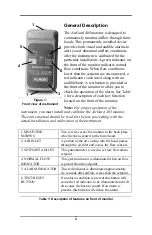
check the operation of the alarm. See Table
1 for a description of each key function
located on the front of the monitor.
Note
:
For proper operation of the
instrument, you must install and calibrate the AirGard 405 monitor.
The entire manual should be read first before proceeding with the
actual installation and calibration of the instrument.
1. MOUNTING
SCREWS
Two screws secure the monitor to the back plate
which is then secured to the fume hood.
2. AIR INLET
A portion of the air coming into the hood passes
through the air inlet and across the flow sensors.
3. SETPOINT ADJUST
This potentiometer is used to set low flow alarm
setpoint.
4. NORMAL FLOW
INDICATOR
This green indicator is illuminated when air flow
is greater than the setpoint.
5. ALARM INDICATOR This red indicator is illuminated approximately
six seconds after airflow is less than the setpoint.
6. TEST/RESET
BUTTON
If no alarm condition is present this button will
cause the red indicator to be illuminated and will
also cause the horn to sound. If an alarm is
present, this button will silence the alarm.
Table 1: Description of features on front of monitor
1
Figure 1:
Front view of instrument
5
4
1
2
6
3
Summary of Contents for AirGard 405
Page 1: ...Model 405 AirGard Fume Hood Monitor OWNER S MANUAL...
Page 14: ......


