5
5
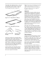
Step 9: Verify that the handle hold button
connector is plugged into the sensor
module as shown in Figure 6.
Figure 6—Hold button connector attachment
Step 10: The meter may be tilted for convenient
viewing by loosening the tilt release
knobs located under the meter. Adjust
the meter to the desired angle and
tighten the knobs.
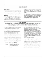
See Figure 7 for various ways to hold the
Electronic Balometer.
Figure 7—Holding Balometer for measurement
To begin using the APM 150 Electronic Balometer
system, proceed to Keypad and Menu selections.
Tip:
Before using the Electronic Balometer, allow
the unit to warm up for 15 minutes to achieve best
possible accuracy (Deactivate Auto Shut-off.) The
meter may be turned on before the hood is set up
to minimize waiting time before taking
measurements.
Alternate Hood Installation
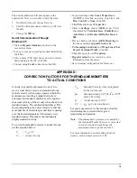
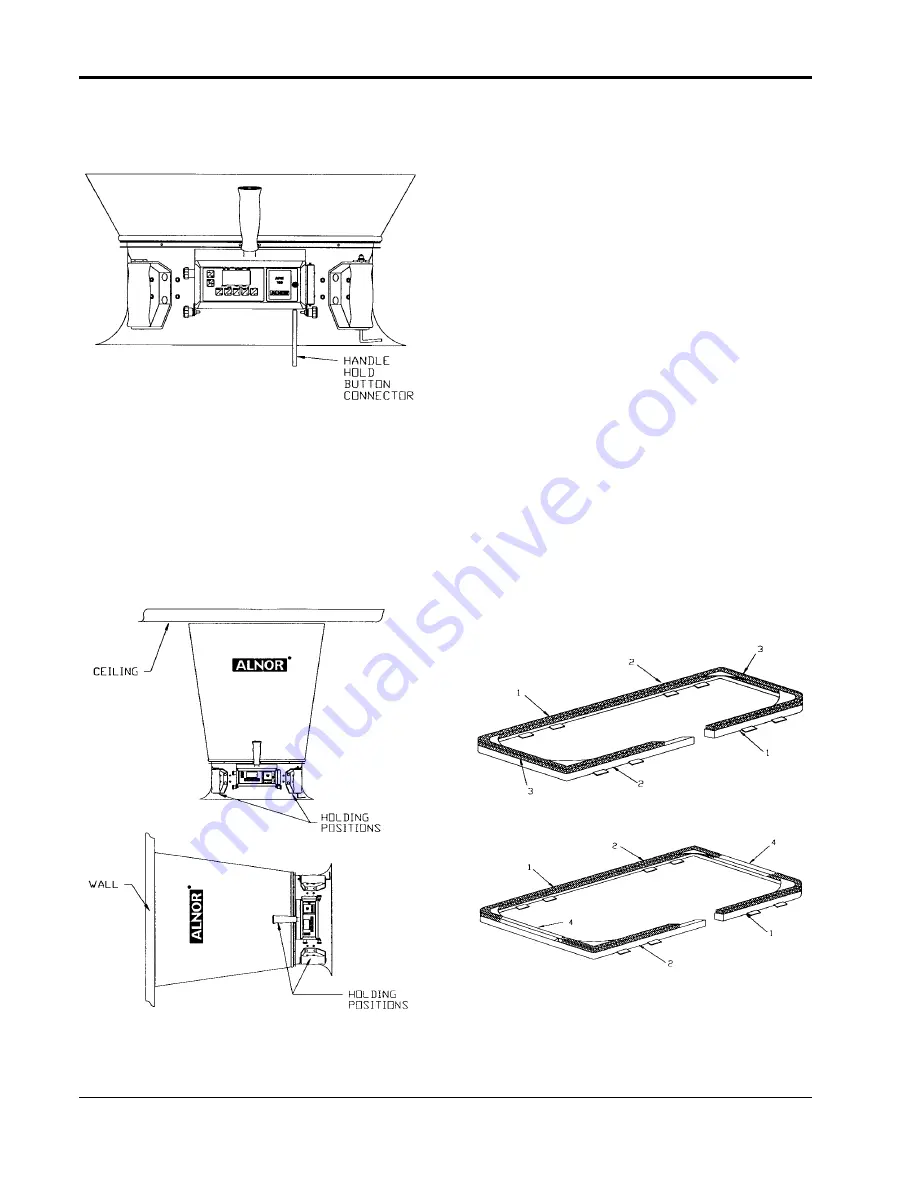
Refer to Figures 8 through 11 to determine the
frame channels needed to assemble any of the
standard sized frames. Select the pieces required
for the frame size desired and assemble with the
aid of the appropriate figure. Each channel is
labeled with its number for easy identification.
Several sections (numbers 1, 3, and 4) consist of a
straight channel portion (each a different length)
and a corner piece. This corner piece has an eyelet
and slot arrangement which mates with a similar
eyelet and slot at the end of the straight portion of
the channel pieces (see Figure 12). These pieces
can be slid together and are self locking by means
of a retention spring. The arrangement forms a
rugged frame which is additionally strengthened
when the hood is attached.
Figure 8—1' x 4' Frame (305 x 1220 mm)
Figure 9—2' x 4' Frame (610 x 1220 mm)
Summary of Contents for APM 150
Page 1: ...Electronic Balometer with APM 150 Meter OWNER S MANUAL...
Page 4: ......
Page 26: ...22 22...
Page 76: ......


