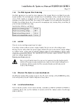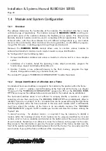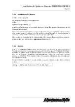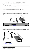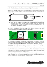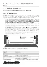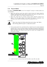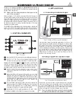
Installation & Systems Manual RUBIDIUM SERIES
Page 18
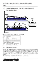
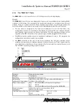
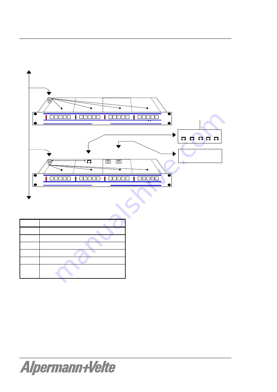
1.3 System Extensions: The RLC Connector and
Further Interfaces
AlVelte
R U B I D I U M SERIES 1
OPER
ERROR
SET
SIGNAL
OPER
ERROR
SET
SIGNAL
OPER
ERROR
SET
SIGNAL
OPER
ERROR
SET
SIGNAL
ADR = 4
ADR = 3
ADR = 2
ADR = 1
RLC
SERIAL
(RS232/RS422)
10/100base-T
AlVelte
R U B I D I U M SERIES 1
OPER
ERROR
SET
SIGNAL
OPER
ERROR
SET
SIGNAL
OPER
ERROR
SET
SIGNAL
OPER
ERROR
SET
SIGNAL
ADR = 4
ADR = 3
ADR = 2
ADR = 1
RLC
TC_link (RS485 Bus)
Hub
Ethernet
Network
Local Remote Control /
Real Time Data Request
Fr
am
e 1
Fr
am
e 2
Pin assignment of the 9-pins DSUB female connector
RLC
:
Pin Description
1 FAIL_A
2 TC_link (RS485,
TR-)
3 TC_link (RS485,
TR+)
4 FAIL_B
5, 6, 7 GND, signal ground
8, 9
Nominal 24 VDC, 3 A maximum.
Not connected at “RUB1 D1”.
1.3.1
The “TC_link” Interface
The “TC_link” interface enables a communication between modules, even between modules
located in different frames. Electrically, it is based on an RS485 interface with a baud rate of
115,000. 256 modules at maximum are allowed to share one TC_link. External cables should
not exceed an overall length of 4000 feet (1200 m). Termination is provided at the fan
module (H1 or Q1 frame) and at the RC module (H3 frame), please refer to the related
chapters.
The communication protocol depends on the module and application.

