Installation & Systems Manual RUBIDIUM SERIES
Page 35
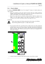
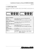
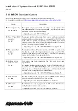
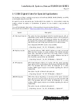
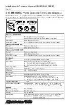
2.2.4
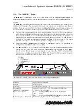
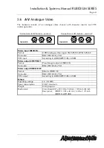
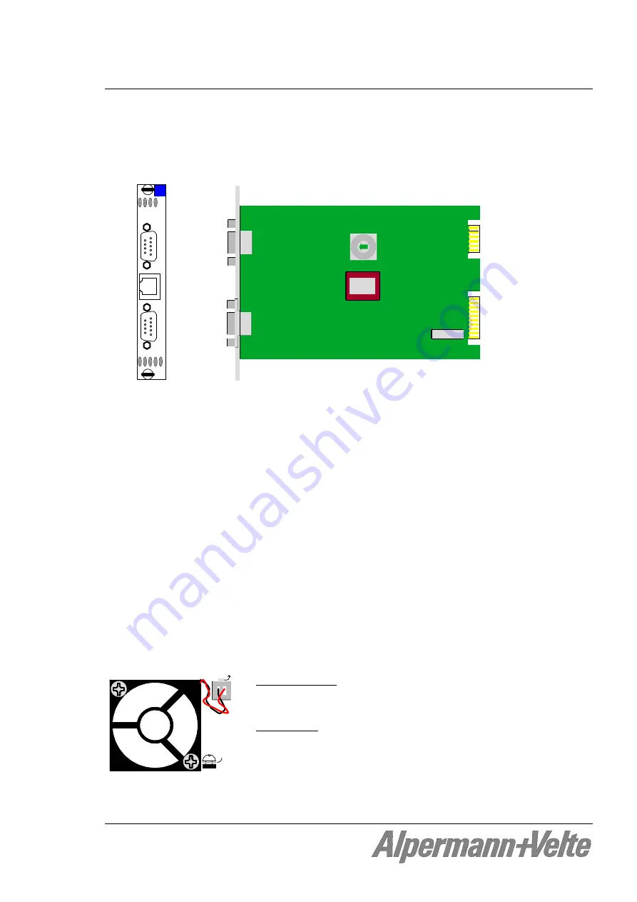
The RC Module: Fan Control, Frame Address, TC_link Termination
The
RUB3 H3
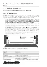
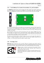
standard frame will be equipped with a RC module. This module contains the
fan control electronic, a fail relay for error detection, a fourfold dip switch and a rotary switch.
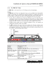
There are two DSUB RLC connectors and a LTC IN connector (future use) at the rear plate.
Al
pe
rm
ann+
Ve
lte
RC
1
1
RLC
RLC
LTC
IN
FAIL
0
on
1 2 3 4
The contacts of the fail relay are normally open during operation, but close if the module fails.
The contacts are (in parallel with the fail relays of all the modules plugged into this frame)
connected to the FAIL_A and FAIL_B pins of the RLC connector of the frame. Mainly this relay
indicates a fan failure.
The fourfold dip switch can be used to terminate the “TC_link” interface (RS485 bus) of the
RLC connector. In a system of one or two frames all the switches should be set to position ON
(= terminated). In a system of more than two frames the switches of the first and the last frame
should be set to position ON, all other to position OFF.
The rotary switch sets the frame number. A system of one frame only gets the number 0 (=
single). In a system consisting of more than one frame the rotary switches should be set to
numbers > 0 in that way that each frame gets a unique number.
2.2.5
Exchange a Fan
RUB3 H3
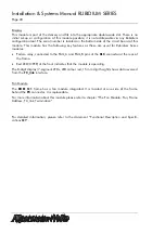
chassis includes two fans. At chassis delivered not before August 2012, each fan
are mounted with two screws and therefore can be easily exchanged. The fans can be reached
behind the front plate: Unscrew both the collar screws, and then fold down the front plate.
toot
h l
oc
k w
ashe
r
Remove a fan: In order to disconnect the connector lift the
release lever and pull out the connector. Now unscrew the
recessed head screws at the fan.
Insert a fan: Attach the fan using two recessed head screws with
toothed lock washer. Do not apply an excessive force. Now plug
the connector.

