simply
adding additional MLS-32L boards. Each MLS-32L board is programmed with an
"address" (1-8) which identifies it from the other MLS-32L boards. Programming is
accomplished by placing a programming jumper over stake-pin pair 1-8 on the MLS-32L board
(refer to drawing C022397-3). Later, you will program each input with its own message. When
programming messages, inputs are identified on the liquid crystal display (LCD) as input 001-
input 256. These will correspond to terminals on MLS-32L boards. Terminals 1-32 on the MLS-
32L board addressed as #1 will correspond to input 001-input 032. Terminals 1-32 on the MLS-
32L board addressed as #2 will correspond to input 033-input 064, respectively. Refer to the
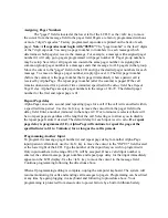
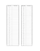
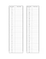
chart Relationship between MLS-32L terminal number, MLS-32L board number and
programming input number
for a complete reference guide.
Installer: Make note of which call
station is wired to each MLS-32L input using the charts located in this manual.
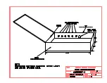
Room wiring is connected to pluggable terminal blocks on the MLS-32L boards, refer to
drawing C030497-1. MLS-32L boards are plugged into the MLS-32L sockets of the MLS-SPU1
board, refer to drawings C022397-4 and C030297-1. Any MLS-32L board number (address) may
be plugged into any of the eight sockets on the MLS-SPU1, the order does not matter. MLS-32L
boards are held securely in place by #6-32 mounting screws going through the "L" brackets of the
MLS-32L and into the MLS-32L mounting posts located in the MLS-EC1 enclosure.
CONNECTING TX125-ENC TRANSMITTER
Refer to drawing #C091905-1 for connection/wiring instructions for the paging
transmitter. Note that the paging data will come out of the COM1 serial port of the MLS-SPU1
processor board. The data will go through two MLS-485's, then after a protocol conversion will
be feed into the TX125-ENC paging transmitter. The MLS-485 devices also function as short-
haul modems. This means that the paging transmitter may be located remotely from the MLS-
SPU1 processor board by up to 2,500'. This may be useful for locating the transmitter in a central
(and high location in multi-story buildings) to achieve optimum paging coverage. One MLS-485
will be located near the MLS-SPU1, (use the modular cable and DB9-MOD6-1 adapter to
connect this MLS-485 to the MLS-SPU1), the second MLS-485 will be installed at whatever
location is chosen for the TX125-ENC transmitter. (Use the PTIP-MOD-3 adapter to connect this
MLS-485 to the TX125-ENC transmitter.) Two pair of unshielded 22 gauge wire is required
between the MLS-485's. Note that the MLS-485's will be powered from the 12VDC power
output of the MLS-SPU1 board.
MAKE SURE to observe voltage polarity when connecting
power to the MLS-485's.
Notice that the two MLS-485's have a mode switch coming out of the end panel. Refer to
drawing #C091905-1 for the correct mode switch position for each MLS-485. Also notice that
each MLS-485 has different firmware installed in it's processor board. The firmware version in
each MLS-485PC is indicated on a label on the bottom of the unit. Again refer to drawing
#C091905-1 for the proper location (at MLS-SPU1 or at TX125-ENC paging transmitter) for
each MLS-485. The MLS-485 that connects to the MLS-SPU board has 485PCTX5 firmware,
the MLS-485 that connects to the TX125-ENC transmitter has 485PCRX5 firmware. Use the
supplied Velcro to mount this MLS-485 next to the TX125-ENC. Mount the TX125-ENC using
the four holes/slots. You provide the mounting screws depending on what type of surface the
TX125-ENC is being mounted to. Mount the TX125-ENC with the antenna oriented vertically.

