ADM-XRC-5T2-ADV User Manual
ADM-XRC-5T2-ADV User Manual
Version 1.0
Table of Tables
Table 1 Local Bus Interface Signal List .................................................................................... 4
Table 2 Voltage and Temperature Monitors............................................................................. 5
Table 3 MGT Clock Connections ............................................................................................. 8
Table 4 User FPGA I/O Bank Voltages .................................................................................. 10
Table 5 DDR Memory Bank Configuration ............................................................................. 10
Table 6 FCN Interface - MGT Links ....................................................................................... 11
Table 7 Board Control Signals ............................................................................................... 12
Table 8 Optical Module Control Signals .................................................................................. 12
Table 9 Pn4 to FPGA Assignments........................................................................................ 13
Table 10 Pn4 I/O Voltage Selection ....................................................................................... 13
Table 11 XMC P15 Connections ............................................................................................ 14
Table of Figures
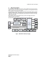
Figure 1 ADM-XRC-5T2-ADV Block Diagram.......................................................................... 3
Figure 2 Local Bus Interface .................................................................................................... 4
Figure 3 JTAG Header ............................................................................................................. 6
Figure 4 Clock Structure........................................................................................................... 7


