background image


______________________________________________________________________ 

Alpha ESS Co., Ltd. 

Page 6 of 29 
 

Your Smart Energy 

Introduction 

The system should be operated in strict accordance with the description in the manual, in 
case that it causes damages or loss to equipment, personnel and property.   

This manual should be kept carefully for maintenance and reparation. 


Operator Requirements 

The operators should get a professional qualification, or trained. 

The operators should be familiar with the whole storage system, including compositions 
and working principles of the system. 

The operators should be familiar with the Product Instruction. 

While  maintaining,  the  maintainer  is  not  allowed  to  operate  any  equipment  until  all  the 
equipment has been turned off and fully discharged. 


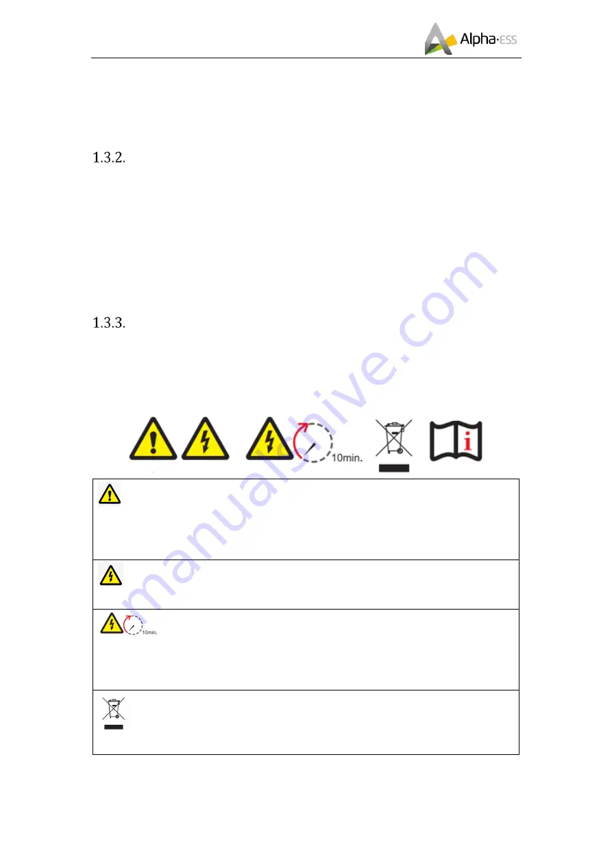
Protection of Warning Sign 

The warning sign contains important information for the system to operate safely, and it is 
strictly prohibited to be torn or damaged. Ensure that the warning sign is always clear. The 
signs should be replaced immediately when damaged. 


  It indicates a hazardous situation which, if not avoided, could result in death or serious 

injury! 

Il indique une situation dangereuse qui, si elle n'est pas évitée, pourrait entraî

ner la mort ou 

des blessures graves! 

  Danger of high voltage and electric shock! 

Risque de haute tension et d'électrocution! 

  Danger to life due to high voltages in the inverter; observe a waiting time of 

10 minutes. 

Danger de mort en raison de tensions élevées dans l'onduleur; respecter un temps d'attente 

de 10 minutes. 

  The product must not be disposed of in household waste! 

Le produit ne doit pas être jeté avec les ordures ménagères! 

Summary of Contents for SMILE-BAT-G3-10.1P

Page 1: ...Installation Manual Energy Storage Battery SMILE BAT G3 10 1P V01 ...

Page 2: ......

Page 3: ...eb www alpha ess de Add Paul Ehrlich Straße 1a 63225 Langen China Alpha ESS Co Ltd Tel 86 0 513 806 868 91 E mail info alpha ess com Web www alpha ess com Add JiuHua Road 888 High Tech Industrial Development Zone 226300 Nantong City Jiangsu Province Australia Alpha ESS Australia Pty Ltd Tel 61 1300 968 933 E mail australia alpha ess com Web www alpha ess com au Add Suite 1 Level 1 530 Botany Road ...

Page 4: ...tatement This manual is under the copyright of Alpha ESS Co Ltd with all rights reserved Please keep the manual properly and operate in strict accordance with all safety and operating instructions in this manual Please do not operate the system before reading through the manual Version Information Version Date Content V01 Jan 26th 2022 First edition ...

Page 5: ...eping 5 Operator Requirements 6 Protection of Warning Sign 6 Setting of Warning Sign for Safety 7 Measuring Equipment 7 Moisture Protection 7 Operation After Power Failure 7 Battery Safety Datasheet 7 General Precautions 9 Parts List 11 Liability Limitation 11 2 Installation 13 Installation Site and Environment 13 General 13 Restricted Locations 14 Barrier to habitable rooms 15 Installation 16 Con...

Page 6: ...isplay 19 Switch On Off 19 LED Display 19 4 Error and Protection Code 21 Protection Code 21 Error Code 21 5 Emergency Situations 23 6 Warranty 24 Warranty 24 Limitation of Liability 24 7 Routine Maintenance 25 Maintenance Plan 25 Operating Environment 25 Equipment Cleaning 25 Cable Terminal and Equipment Inspection 25 Notes 25 Appendix Datasheet 27 ...

Page 7: ...he battery from operating outside design limitations Expandability This battery pack can be easily expanded as battery system named as SMILE G3 BAT 10 1P Single module SMILE G3 BAT 10 1P II SMILE G3 BAT 10 1P 2 SMILE G3 BAT 10 1P III SMILE G3 BAT 10 1P 3 SMILE G3 BAT 10 1P IV SMILE G3 BAT 10 1P 4 SMILE G3 BAT 10 1P V SMILE G3 BAT 10 1P 5 SMILE G3 BAT 10 1P VI SMILE G3 BAT 10 1P 6 Specifications Fi...

Page 8: ...the equipment has been turned off and fully discharged Protection of Warning Sign The warning sign contains important information for the system to operate safely and it is strictly prohibited to be torn or damaged Ensure that the warning sign is always clear The signs should be replaced immediately when damaged It indicates a hazardous situation which if not avoided could result in death or serio...

Page 9: ...ment For ensuring the electrical parameters to match requirements related measuring equipment are required when the system is being connected or tested Ensure that the connection and use matches specification in case of electric arc or shock Moisture Protection It is very likely that moisture may cause damages to the system Repair or maintaining activities in wet weather should be avoided or limit...

Page 10: ...emperatures and pressures encountered during normal use As a result during normal use there is no physical danger of ignition or explosion and chemical danger of hazardous materials leakage However if exposed to a fire added mechanical shocks decomposed added electric stress by misuse the gas release vent will be operated The battery cell case will be breached at the extreme Hazardous materials ma...

Page 11: ...gh humidity Do not mount the inverter and the battery pack in areas containing highly flammable materials or gases If moisture has penetrated the system e g due to a damaged enclosure do not install or operate the system Do not move the system when it is already connected with battery modules Secure the system to prevent tipping with restraining straps in your vehicle The transportation of AlphaES...

Page 12: ...ntroduction CAUTION Risk of injury through lifting or dropping the system The battery is heavy There is risk of injury if the battery is lifted incorrectly or dropped during transport or when attaching to or removing from the wall Lifting and transporting the inverter and battery must be carried out by more than 1 people ...

Page 13: ... by non AlphaESS technician System design and installation are not in compliance with standards and regulations Failure to comply with the local safety regulations VDE for DE SAA for AU Transport damage including painting scratch caused by rubbing inside packaging during shipping A claim should be made directly to shipping or insurance company in this case as soon as the container packaging is unl...

Page 14: ... of the user manual the installation guide and the maintenance regulations Improper use or misuse of the device Insufficient ventilation of the device The maintenance procedures relating to the product have not been followed to an acceptable standard Force majeure violent or stormy weather lightning overvoltage fire etc Damages caused by any external factors ...

Page 15: ...an indoor location In SN YYMMXXXX Where battery systems are installed within a room shall be located so that access to the battery is not obstructed by the structure of the building fixtures and fittings within the room SMILE BAT G3 10 1P adopts natural ventilation The location should be clean dry and adequately ventilated The room s entry doors and panels shall open in the direction of egress and...

Page 16: ...nditioning unit or any other appliance c within 600 mm of any exit d within 600 mm of any window or ventilation opening e within 900 mm of access to 240 Vac connections f within 600 mm of side of other equipment A SMILE BAT G3 10 1P installed in any corridor hallway lobby or the like leading to a fire exit shall ensure sufficient clearance from the SMILE BAT G3 10 1P for safe egress and no less th...

Page 17: ...er may be placed between the SMILE BAT G3 10 1P and the surface of a wall or structure Where the SMILE BAT G3 10 1P is located on or within 300mm of the wall or structure separating it from the habitable room the barrier shall extend i 300 mm beyond the vertical sides of the SMILE BAT G3 10 1P ii to the extent of the bottom of the SMILE BAT G3 10 1P Where the top of the SMILE BAT G3 10 1P is withi...

Page 18: ... depth of each hole should be about 7 cm Step 3 Insert the expansion tube into the drilled hole Pass the expansion screw through the gasket and lock with a screwdriver Installation method The location of bolted wall is the mark of the red circle is the bolted wall Drilled the wall with a Φ10 drill bit to a depth of 80mm inserted the gray expansion pipe into the wall and then tightened the expansio...

Page 19: ... 29 Your Smart Energy Installation Connect to inverter Step 1 Connect the power cable from the battery to the inverter Please put the power cable in the limit hole Step 2 Connect the communcation cable from the battery to the inverter 6 10mm PH2 2 5N m M5 10 Negative Power Cable Positive Power Cable ...

Page 20: ..._____________________________________ Alpha ESS Co Ltd Page 18 of 29 Your Smart Energy Installation Connect Expansion Batteries Connect the power cables and BMS cable between the batteries as the picture shown below Communication Cable ...

Page 21: ... button will light up as well Switch off Pressing the power button for 5 seconds Turns off battery modules Figure 3 1 LED Display LED Display In normal condition LED display indicates the SOC as the figure below LED Ring SOC Description Standby Green light flickering 1 s Work Green light flickering 10s SOC 20 The first light 3S flashes once 20 SOC 25 The first grid light is always on 25 SOC 45 The...

Page 22: ..._______________________________ Alpha ESS Co Ltd Page 20 of 29 Your Smart Energy Switch On Off and Display 75 SOC 95 The fourth light 3S flashes once SOC 95 The fourth light is always on PS ESD monitoring is achieved via inverter monitoring ...

Page 23: ...nt discharge 8 Cell overvoltage 9 Cell under voltage 11 Low temperature charge Error Code LED Ring Error Code LED display Description Troubleshooting Red light flickering every 1 seconds Error 01 Hardware error Wait for automated recovery In case problem is not resolved call in for repair Error 02 Hardware error Error 03 Hardware error Error 05 Hardware error Error 06 Circuit Breaker Open Close ci...

Page 24: ...re version inconsistent Call installation for repair Error 12 Multi master Restart all batteries Error 13 MOS over temperature Power off the battery and turn on the battery after 30 40 minutes Error 14 Insulation fault Error 15 Total voltage fault NOTE In the case of parallel mode or work mode if Protection 09 appears and the power button is pressed 5 times within 10 seconds the BMS will be forced...

Page 25: ... or gas If one is exposed to the leaked substance immediately perform the actions described below Inhalation Evacuate the contaminated area and seek medical attention Contact with eyes Rinse eyes with flowering water for 5 minutes and seek medical attention Contact with skin Wash the affected area thoroughly with soap and water and seek medical attention Ingestion Induce vomiting and seek medical ...

Page 26: ...umber or seals by non AlphaESS technician System design and installation are not in compliance with standards and regulations The Product has been improperly stored in dealer s or end user s premises Transport damage including painting scratch caused by movement inside packaging during shipping A claim should be made directly to shipping or insurance company as soon as the container packaging is u...

Page 27: ...e year depending on the site environment and dust content etc Ensure that the ground is clean and tidy keep the maintenance access route unblocked and ensure that the warning and guiding signs are clear and intact Monitor the temperature of the battery module and clean the battery module if necessary Cable Terminal and Equipment Inspection Every six months to one year Check if the cable connection...

Page 28: ...of capacitors down to safe voltage Use a multi meter to ensure the equipment is completely uncharged The equipment should be repaired by professional staff and it is strictly for bidden for maintenance staff to open equipment on their own Appropriate protective measures should be taken while maintaining such as insulated gloves shoes and anti noise ear plugs Life is priceless Make sure no one woul...

Page 29: ...in parallel Capacity 10 1 20 2 30 2 40 3 50 4 60 5 kWh Usable Capacity 9 6 19 2 28 7 38 3 47 9 57 5 kWh Monitoring Parameters System voltage current cell voltage cell temperature PCBA temperature Communication CAN and RS 485 compatible Certification Transportation UN38 3 Safety IEC 62619 IEC 63056 IEC 62040 The model will be defined as SMILE G3 BAT 10 1P II SMILE G3 BAT 10 1P III SMILE G3 BAT 10 1...

Reviews: