Installation
14
900-0184-01-00 Rev A
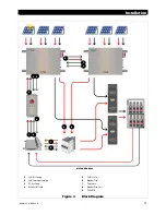
Connection Information
Combiner
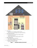
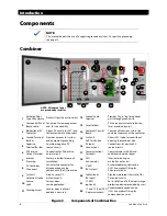
The combiner box can take input circuits from up to six PV subarrays. It provides a single PV output
which is connected to the load center and one pole of the RTB. See Figure 4 on page 15.
The combiner’s control board receives power from the RSI (
2
). It also sends status information to the RSI (
3
).
Both sets of wires must be connected for correct PVRSS operation.
The communication wires may be run in the same conduit as the PV wire only if the communication wiring
is rated for the highest system voltage.
Up to six combiners can be used in a single system with a single RSI. The control wires must be placed in
series (“daisy chained”) between combiners.
Regardless of the number in use, the last combiner must have a jumper placed across its sensing terminals
to close the circuit. If only one combiner is present, the jumper must be placed there.
RSI
The RSI communicates with the combiner box (and with any additional combiners connected to it).
It also communicates with the Circuit Breaker Control box, BKR-CTRL-DC, and RTB connected to it.
See Figure 4 on page 15.
It receives power (
1
) from the BKR-CTRL-DC or a similar power supply.
It sends power (
2
) to the combiner(s) control board.
It receives AFCI (
3
) status information from the combiner(s).
It receives PVRSS status information from the BKR-CTRL-DC (
4
) and the combiner(s) (
5
).
It sends RTB disconnect commands (
6
) to the BKR-CTRL-DC.
Both sets of wires must be connected for correct PVRSS operation.
BKR-CTRL-DC
The BKR-CTRL-DC connects to the battery bus in the load center. See Figure 4 on page 15.
It sends 24-volt power to the RTB (
8
) and the RSI (
1
) (which in turn powers the combiner).
The positive wire to the load center must be protected with the following fuse type:
3AG Cartridge, 3A slow-blow, 10kA@125VDC.
This box receives a plug which must be manually wired in advance with the appropriate conductors.
CAUTION: Equipment Damage
The 24-volt conductor is not grounded and is not to be connected to chassis or any
other grounding system.
RTB
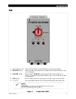
The remote-trip breaker facilitates part of the PVRSS function by removing the charge controller from
the PV circuit. It has connections for the trip sense function (
7
), the breaker-trip coil (
8
), and the PV
input (
9
). See Figure 4 on page 15.
The RTB takes the place of the PV input disconnect which is normally installed in the load center.
When multiple combiners are in use, multiple RTB poles may be required. PNL-75D-DC-RT has dual poles for
two combiners. PNL-75Q-DC-RT has quadruple poles for four combiners.
When six combiners are in use, PNL-75D-DC-RT and PNL-75Q-DC-RT should both be installed. For this
installation, the RTB control and coil connections should be wired in parallel.

