9
Subject to technical amendments without prior notice | 83055400iUK – 2.1 | ait-deutschland GmbH
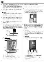
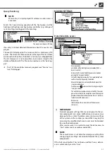
External return flow sensor
The return flow sensor (optional accessory) is functionally-rele-
vant for hydraulic integration of an isolating tank (multifunction
tank .). This has to be installed as follows:
ZUP
TRLext
HUP
1
Separation or multi-functional storage tank
2
Circulation pump in the separation storage
tank (heat pump circuit)
3
Circulation pump from the separation storage
tank (heating circuit)
4
External return sensor (Ø = 6 mm)
ZUP Charging loop, heat pump
HUP Discharging loop, heating circuit
Connect the return flow sensor coming from the isolating tank to
the circuit board of the heating and heat pump regulator.
Dismantling
DANGER
Danger of fatal injury due to electric current!
Electrical connections may be installed only by qualified
electricians.
Before opening the unit, disconnect the system from the
power supply and secure it from being switched back
on!
Softwareupdate / ‑downgrade
Software updates/downgrades can be carried out via the USB in-
terface on the control unit of the heating and heat pump control-
ler.
1. Expose the USB interface on the control unit.
Part 1 of the controller manual, program area “Service“, sec-
tion “Basic Information on the operation“
2. Insert a USB stick with the software into the USB interface
and follow the on-screen instructions.
IMPORTANT
Only install updates/downgrades that are cited as “valid
updates” (“Gültiges Updates”) in the screen list.
Switching on / Commissioning
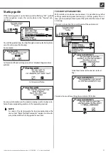
When switching on the controller voltage or after a restart of the
heating and heat pump controller (reset), a self-test is carried out
to check whether the basic components of the heat pump system
are available.
The components displayed vary depending on the heat
pump type.
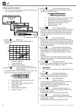
The self-test (POST = Power on startup) can take up to
5 minutes (Time-out).
Once all the basic components of the system are detected within
5 minutes, the system is ready for operation.
NOTE
If the self-test fails, an emergency mode is activated, if at
least the necessary components have been detected.
page 12, “Emergency mode“
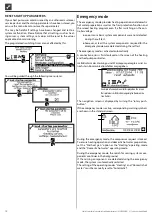
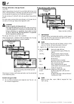
If the system is ready for operation but not yet configured (initial
switching on), then the language selection is displayed first.
Select the display language: part 1 of the controller manual,
section “Basis information on the operation“.
NOTE
The language must be confirmed.
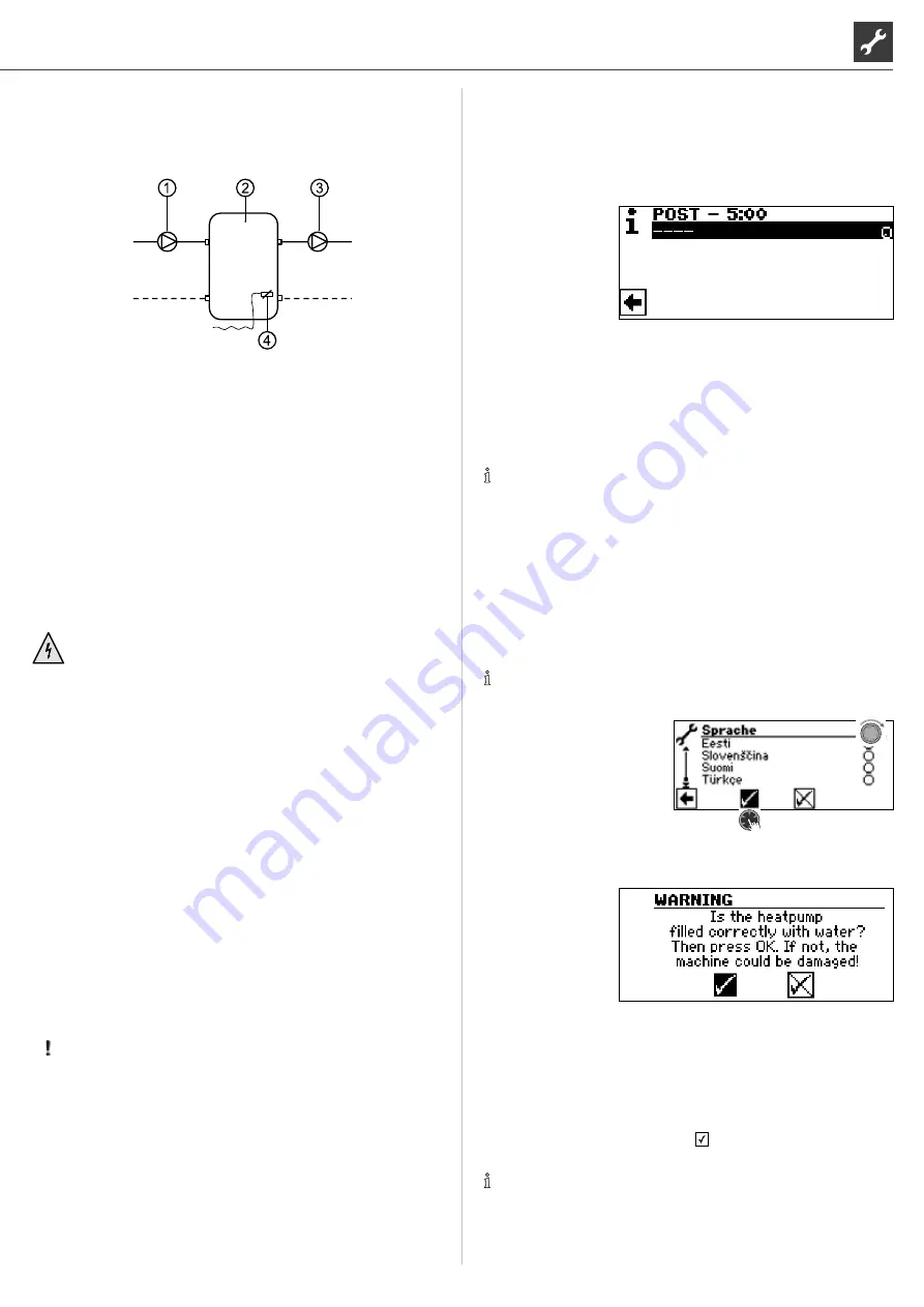
Then click on the navigation arrow in the language display. After
that a security question appears:
The security question always appears when the control-
ler voltage is switched on or after a restart of the heating
and heat pump controller (reset).
This screen is no longer displayed if the heat pump or
ZWE1 has more than 10 operating hours.
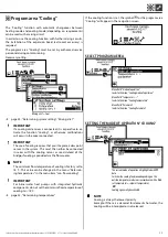
No ZWE (additional heat generator) is released by the controller
until the display is confirmed with .
NOTE
No heat generator runs during a cold start of air/water heat
pumps.


