background image

27

Subject to change without notice  |  83031200dUK  |  ait-deutschland GmbH

-F1
0

-F1
3

A1

A2

-K1
3

-F

14

A1

A2

-K

14

-F

11

A1

A2

M

ZI

P

M

Z

UP

ZIP

ZW
2

M

X

52

-X8

N

5

ZW2/SST

A6

ZW
1

Z

W1

K

13

1

0

-X
5

4

X1
/X5

F

10

5

5

F

11

L1

A1

5

3~N/PE/400V/50Hz

PE

TB1

HUP

BU
P

TA

11

-X

12

A2

H

UP

X

8

PE

-X1

MZ1

N

PE

Z

W

2/S

S

T

Z

W2

4

R

FV

MI

S

7

A1

L

M

-X0

2

N

A3

V

B

O

Z

UP

-X
3

-X2

Air 

water 

outside

X7

T

BW

1

MA1

E

V

U

HUP

3

7

A

4

GND

2

9

3~PE/400V/50Hz

FP1

BUP

N

T

er

m

in

als

Z

W1

N

am

e

MOT

1

2

TBW

8

3

PE

6

A2

GND

A4

X

0-

X

4

VBO

ZUP

8

3

1

B

UP

A3

A6

1

1

ZW
2

X

12

Z

IP

In

fo

rm

at

io

n

 o

n f

us

es

 c

an

 b

e f

ou

nd

 in

 th

e t

ec

hn

ic

a

l d

at

a

-X

52

F1
4

-X7

Z

W1

K

14

A5

A5

3~N/PE/400V/50Hz

RFV

F1
3

L1

TB1

L1

ZW1

-X4

RFV

F

P1

N

M

OT

2

T

B1

1~N/PE/230V/50Hz

E

VU

GND

T

RL

B10 A

9

M

A

1/M

IS

TA

GND

P

EX

TA

Le
g

e

n

d:

ASD

TBW

TRL

PE

GND

GND

1

04

12

PEX

6

EVU

MZ
1/MI

S

U

K

83
1164

F

unc
tion

C

ont
rol

ler

 boar

d;

 A

ttent
ion:
 I

-m

ax

 =

 6

A

/23

0V
A

C

H

eat
 pu

m

p

S

ub-
di

str

ibu

tion

 uni
t i

nt

er

n

al

 ins

tal

lat

ion

T

er

m

in

al

s i

sw

itc

box
 w

al

l r

egul

at

or

H

ot

 w

a

ter

 o

r buf
fe

r s

tor

age

 tank

H

ot

 w

a

ter

 o

r buf
fe

r s

tor

age

 tank

3-

pol
. C

u

t out
 c

om
pr

es

sor

; A

ttent
ion:
 R

ight
-hand

 rot

. fi

el

d i

s m

andat

or

y!

C

ut

 ou
t c

ont
rol

ler

 uni
t

C

ut

 o

ut

 a

ux

ilia

ry

 heat

ing

 1

C

ut


ou

t


a

ux

ili

a

ry


heat

ing


2

C

ont
ac

tor

 el

e

ctr

ic

 he

at

in

el

e

m

ent
 b

uf

fe

r t

ank

C

ont
ac

tor

 el

e

ctr

ic

 he

at

in

el

e

m

ent
 h

ot

 w

at

er

 or

 bu

ffer

 tank

H

ot

 w

a

te

r c

irc

ul

ati

ng

 pum

p/

sw

itc

hi

ng

 v

al

ve

E

ne

rgy

 s

uppl

ier

 c

ont
ac

t; c

los

e

d on

 rel

eas
e;

 br

idg

e i

f n

bl

oc

king

 int

e

rv

al

P

ump


for


m

ix

in

g


ci

rcu

it


1

H

eat
ing

 c

irc

ui

t c

irc

ul

at

ing

 pum

p

C

har
ge/
di

sc

har
ge/
cool
ing

 m

ix

e

r 1

 o

pen

C

har
ge/
di

sc

har
ge/
cool
ing

 m

ix

e

r 1

 c

los

e

d

O

ver

loa

d pr

ot

ec

tion;
 in

ter

nal
ly

 w

ire

d

N

o f

unc
tion

A

cc

es

sor

ies

: R

em

ot

cont
rol

E

xter

nal
 s

ens
or

S

en

sor

 m

ix

ing

 c

irc

ui

t 1

Ho
t


w

a

ter


gaug

e/

ther
m

os

tat

E

xter

nal
 ret

ur

n s

ens
or

V

en

tilat

or

; i

nt

er

na

lly

 w

ired

T

er

m

in

al


stri

ps


on


con

trol

le

r boar
d (

see

 s

tic

ker

)

P

lugs
 on

 c

on

trol

ler

 boar

d (

see

 s

tic

ke

r)

T

er

m

in

al

 s

trip

 in

 s

w

itc

box
 w

al

l r

egu
lat

or

; N

/P

E

 di

str

ibut
ion

 for

 ex

te

rnal
 2

30V
 de

vic

es


D

is

tribut
ion


box


in


h

eat


pum

p

;


pow

er


sup

pl

y


out
put


co

m

pr

es

sor

P

lug

 on

 s

w

itc

h b

ox

 hea
t pum

(c

ont
rol

 line

)

P

lu

g


on


sw
itc

h


b

ox


hea
t


pum

p


(g

au

ge


lin

e)

Auxiliary 

circulation 

pump

C

irculation 

pump

C

ont
rol

 s

ignal

 of

 add

itional
 heat

 g

en

er

at

or

 1

C

ont
rol

 s

ignal

 of

 add

itional
 heat

 g

en

er

at

or

 2

T

er

m

inal
 di

agr
am

 LW
 250A

 / 310A

8311

64

A

chi

m

 P

fle

g

er

0

4.12
.20
09

-

P

EP
 0

20

/2

00

9

1

2

3

4

5

6

7

8

9

10

11

12

13

14

15

16

1

2

3

4

5

6

7

8

9

10

11

12

13

14

15

16

1

/1

1

0

4.1

2.

20
0

9

1

0X

449;

A

chi

m

 P

fleg
er

10X

547;

B

la

tt-N

r.

Z

us

ta

nd

Ä

nde
ru

n

g

B

ea
rb.

D

at

u

m

N

am
e

B

l v

o

n A

n

z

D

at

u

m

LW 300A

Terminal diagram

Summary of Contents for LW 300A

Page 1: ...UK 83031200dUK Air Water Heat Pumps Outdoor installation Operating Manual LW 300A ...

Page 2: ...tem 12 7 Pressure relief 13 8 Buffer tank 13 9 Circulating pumps 13 10 Domestic hot water preparation 13 11 Domestic hot water tank 13 12 Electrical installation 14 13 Flushing filling and venting 15 13 1 Heating water quality 15 13 2 Flush fill and vent the heating circuit 16 14 Insulation of hydraulic connections 16 15 Set the overflow valve 16 16 Commissioning 17 17 Maintenance 17 17 1 Basic pr...

Page 3: ...ing manual of the heating and heat pump controller Brief description of the heat pump controller Operating manual of the Comfort board 2 0 accessories Log book 1 3 Symbols and markings Identification of warnings Symbol Meaning Safety relevant information Warning of physical injuries DANGER Indicates imminent danger resulting in severe injuries or death WARNING Indicates a potentially dangerous sit...

Page 4: ...s must be instructed and if necessary supervised by persons experienced in handling the product and who are re sponsible for safety Children must not play with the product The product may only be opened by qualified personnel All instructional information in this operating manual is solely directed at qualified skilled personnel Only qualified skilled personnel is able to carry out the work on the...

Page 5: ...action Requirements for minimum scale and corrosion damage in hot water heating systems Proper planning design and commissioning Closed system with regard to corrosion Integration of an adequately dimensioned pressure maintaining device Use of demineralised heating water VE water or water corresponding to the VDI 2035 norm Regular servicing and maintenance If a system is not planned designed start...

Page 6: ...circuit and hose for condensate discharge connected on heat pump side 3 2 Layout Basic components NOTE This section essentially names the compo nents relevant for fulfilling the tasks described in this operating manual 1 Fan 2 Water connection side Hydraulic connections and junction box for mains connection each inside the unit 3 Area behind the facing panel cooling circuit components with condens...

Page 7: ... to rise and there fore the temperature too The gaseous refrigerant at a high temperature is liquefied condenser The high temperature is hereby discharged to the heating water and is used in the heating circuit The liquid refrigerant at a high pressure and high tempera ture is depressurised expansion valve The pressure and temperature drop and the process begins again The heated heating water can ...

Page 8: ...o the housing and the unit components due to heavy objects Do not place any objects on the unit which are heavier than 30 kg IMPORTANT Do not tilt the unit more than a maximum of 45 in any direction 5 1 Scope of supply Heat pump with air flow baffles The accompanying parts package contains 20 washers and screws for fixing the air flow baf fles Documents manuals ERP data and label Nameplate sticker...

Page 9: ...e air outlet area of the heat pump is permeable to water Unpacking 1 Remove plastic films Ensure that you do not dam age the unit 2 Dispose of the transport and packaging material in an environmentally friendly way and in accord ance with local regulations Set up the unit CAUTION In the air outlet area the air temperature is approx 5 K below the ambient temperature Under certain climatic condition...

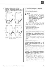
Page 10: ...ore continuing with any other work 1 If you have not already done so remove low er facing panels on the switch cabinet and water connection side of the unit 1 1 To do so loosen the two quick release screws on the lower facing panels 1 2 Pull each facing panel forward detach from the unit and set securely aside Example Removing the lower facing panel on the switch box side 2 Remove upper facing pan...

Page 11: ...nstallation 4 1 Suspend air flow baffles on the brass bushings on the top side of the frame Example Air flow baffle on the fan side 1 Eyelet on air flow baffle 2 Brass bushing on frame 4 2 Bolt air flow baffles to the frame on the switch box side and water connection side Example Screw the air flow baffle on the fan side 5 Return top cover to frame 6 Suspend upper facing panels in the top cover Bo...

Page 12: ...es of the heating circuit via vibration decouplers They must be installed in order to prevent damage from vibrations to the pipes NOTE If an existing system is being replaced the old vibration decoupling may not be reused Vibration decouplers are available as acces sories 1 Hot water inflow return flow connection 2 Hot water outflow forward flow connection 3 Condensate water hose 4 Install the con...

Page 13: ... hot water flow rate required Technical data scope of supply page 19 10 Domestic hot water preparation Domestic hot water heating with the heat pump re quires an additional hot water circuit parallel to the heating circuit Make sure that the heating water charge is not channeled through the buffer tank of the heating circuit Hydraulic connection instructions 11 Domestic hot water tank If the heat ...

Page 14: ...d from there on to the fuse box 6 Connect power cable to power supply IMPORTANT If using the unit in 3 230V systems please note that the residual current circuit breaker RCCB used must be AC DC sensitive Heat pump side connection of the control and sensor wires The heat pump is connected to the heating and heat pump regulator by means of the control and sensor wires They are connected at the elect...

Page 15: ...n after filling the system If the required water quality is not achieved con sult a company specialising in the treatment of he ating water Keep a system log for hot water heating systems in which relevant planning data is entered VDI 2035 Antifreeze in the heating circuit For air water heat pumps installed outdoors it is not necessary to fill a water antifreeze mixture into the heating circuit Th...

Page 16: ...E The activities in this section are only necessary for the integration of storage tanks in series Complete the work steps quickly otherwise the maximum return temperature may be exceeded and the heat pump switches to high pressure fault Turn the adjusting knob at the overflow valve to the right to increase the temperature difference the temperature drop turn it to the left to reduce it 9 System i...

Page 17: ...ries Send notice of completion for heat pump systems and general checklist to the manufacturer s local partner 4 Arrange for the heat pump system to be com missioned by the manufacturer s authorised after sales service for a fee 17 Maintenance NOTE We recommend that you conclude a mainte nance agreement with an accredited heating company 17 1 Basic principles The cooling circuit of the heat pump r...

Page 18: ... water 17 4 Yearly maintenance Record the quality of the heating water analytically In case of deviations from the specifications take suitable measures without delay 18 Faults Read out the cause of the fault via the diagnostics program of the heating and heat pump controller Contact the local partner of the manufacturer or the factory s customer service Have the fault message and unit number to h...

Page 19: ...ure bar 3 Circulation pump control range min I max l h Hot gas use Flow rate pipe dimensioning l h Free pressing Pressure loss Flow rate bar bar l h General unit data Total weight kg 480 Weight of individual components kg kg kg Refrigerant type Refrigerant capacity kg R448A 10 0 Electrics Voltage code all pole fuse protection for heat pump A Voltage code all pole fuse protection for heat pump elec...

Page 20: ...5 30 35 Temp C Pe kW 0 000 0 025 0 050 0 075 0 100 0 125 0 0 1 0 2 0 3 0 4 0 5 0 6 0 7 0 8 0 9 0 10 0 m h p bar p 15 20 25 30 35 40 45 50 55 60 65 25 20 15 10 5 0 5 10 15 20 25 30 35 40 Temp C Temp C Legende UK823310a Volume flow heating water Temp Temp Temperature heating water Temp Temp Temperature heat source Qh Qh Heating capacity Pe Pe Power consumption COP COP Coefficient of performance effi...

Page 21: ... 2 1 A B C D E F 4 3 2 1 b a Zust Ä Ä Ä Schutzvermerk ISO 16016 beachten Ä Ä P a b Keys UK819326b All dimensions in mm A Front view B Side view C Plan view Section without façade and shrouds 1 Heating water outlet flow R 1 1 2 2 Heating water inlet return R 1 1 2 3 Condensate hose outside Ø 36x3 4 Baseplate LR Air direction LW 300A Dimensional drawings ...

Page 22: ...DIN 34 beachten A B C D E F 4 3 2 1 Zust Keys UK819327 All dimensions in mm A Front view C Top view Minimum clearances 1 Recess in base 2 Local heat pipe for heating water forward return flow 3 Empty pipe for electric cables minimum diameter 70mm 4 Condensate discharge minimum diameter 50mm 5 Water permeable surface gravel in the air outlet area 6 Base LR Air direction Installation plan LW 300A ...

Page 23: ...58 1258 1258 715 800 1350 3000 1500 C LR LR LR LR 4 3 2 1 A B C D E F 4 3 2 1 Zust Ände Schutzvermerk ISO 16016 beachten PEP Keys UK819512 All dimensions in mm C Top view LR Air direction A maximum of two sides may be closed along the dash two point line LW 300A Installation plan Cascade 1 2 ...

Page 24: ...258 1258 1350 1350 715 3000 715 3000 LR C LR LR LR 4 3 2 1 A B C D E F 4 3 2 1 Z Schutzvermerk ISO 16016 beachten Keys UK819512 All dimensions in mm C Top view LR Air direction A maximum of two sides may be closed along the dash two point line Installation plan Cascade 2 2 LW 300A ...

Page 25: ...25 Subject to change without notice 83031200dUK ait deutschland GmbH LW 300A Separation buffer tank ...

Page 26: ...mfort board Expansion board 29 Dirt trap 0 6 mm mesh 15 Mixer circuit three way mixer MK2 3 discharge r o t a l u g e r e c n e r e f f i d e r u t a r e p m e T 7 1 l a n o i t p o g n i l o o c r o f t a t s o m r e h t m o o R 0 0 1 x i m e n i r b r ü f y a r t l l i p S 0 3 e g r a h c 2 K M r e x i m y a w r u o f t i u c r i c r e x i M 9 1 r e m o t s u c y b d e i l p p u s s l o r t n o ...

Page 27: ...xiliary heating 2 Contactor electric heating element buffer tank Contactor electric heating element hot water or buffer tank Hot water circulating pump switching valve Energy supplier contact closed on release bridge if no blocking interval Pump for mixing circuit 1 Heating circuit circulating pump Charge discharge cooling mixer 1 open Charge discharge cooling mixer 1 closed Overload protection in...

Page 28: ... absolutely necessary 3 PE 400V 50Hz VD1 VD2 VENT N1 N2 M1 M2 G1 Sump heating for compressor 1 Sump heating for compressor 2 Nozzle heating fan Motor protection fan Fan fuse 6 3 A Fan Contactor for compressor 1 Contactor for compressor 1 Network protection fan Triangle contactor fan Star contactor fan Compressor Compressor Starting current limit compressor Starting current limit compressor Thermos...

Page 29: ... K4 K5 X10 X12 Y1 Y2 Bypass compressor X12 X10 2 X10 3 X10 X10 4 X10 X10 N X10 1 X10 L X10 b2 a1 c4 B10 P UK 817455 Legend Defrosting pressostat High pressure switch Low pressure switch Low pressure switch Contactor for compressor 1 Contactor for compressor 1 Network protection fan Triangle contactor fan Star contactor fan Terminal in switch box heat pump Plug on switch box heat pump control line ...

Page 30: ...ÜBERSETZUNG KEINE ÜBERSETZUNG AND KEINE ÜBERSETZUNG KEINE ÜBERSETZUNG KEINE ÜBERSETZUNG Code KEINE ÜBERSETZUNG 00 EFS KEINE ÜBERSETZUNG X52 Equipement Function R2 R3 R4 R5 R6 R10 X52 TWE TWA TRL TVL THG CW Plug on switch box heat pump gauge line TWE TWA TRL TVL THG CW X10 29 X10 30 X10 Legend UK 817455 If installed heat source input gauge If installed heat source outlet gauge Return sensor Flow se...

Page 31: ...31 Subject to change without notice 83031200dUK ait deutschland GmbH ...

Page 32: ...ait deutschland GmbH Industriestraße 3 D 95359 Kasendorf E info alpha innotec de W www alpha innotec de alpha innotec an ait deutschland GmbH brand UK ...

Reviews: