Page 14
AM-64x DAT High Capacity Tape Drives
PDI-00649-00, A01
Front Bezel Removal and Modification
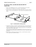
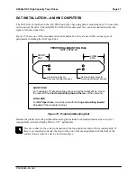
Your DAT drive product installation kit includes instructions describing how to modify your front bezel.
The modification requires you to make a half-height 5.25” cutout if you are installing a DAT drive only,
or a full-height 5.25” cutout if you are installing a DAT drive along with a new (or existing) floppy or
streaming tape drive.
1. Follow the instructions in your computer Owner's Manual for removing the top cover.
2. Unplug the ribbon cable that links the display panel on the computer's front bezel to your CPU
board.
3. Remove the Phillips-head screws holding the front bezel to the computer's chassis.
4. Follow the bezel modification instructions included with your installation kit, then reinstall the
bezel on your computer.
5. Don't forget to plug the display panel cable back into your CPU board.
Building and Installing the DAT Drive Mounting Assembly
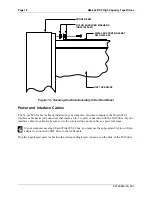
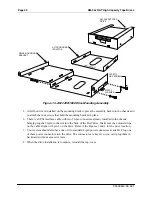
The DAT drive mounting assembly is the same for both pedestal and rack mount computers. The
assembly consists of three pieces; one plastic mounting base, one DAT drive, and one metal support
bracket. The following steps describe how to put the assembly together:
1. Set the drive on top of the plastic mounting base with its status LEDs nearest the plastic
mounting base. This insures the drive is in the proper position for both pedestal and rack mount
computers. Also, pin-1 on the DAT drive's SCSI connector has the same orientation as the other
SCSI devices in your computer.


