background image

Part No:  ECC-125 

   ECC-STAND

   ECC-TABLE

103 Bauer Drive, Oakland, NJ 07436 • 800-648-7229 • Fax: 800-286-0114

www.alpha-tools.com

Alpha

®

 Ecocutter

Dry Tile Cutting System

Instruction Manual

MANUAL

Version 5

Summary of Contents for ECC-STAND

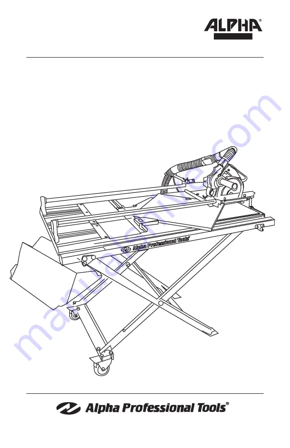
Page 1: ...Part No ECC 125 ECC STAND ECC TABLE 103 Bauer Drive Oakland NJ 07436 800 648 7229 Fax 800 286 0114 www alpha tools com Alpha Ecocutter Dry Tile Cutting System Instruction Manual MANUAL Version 5 ...

Page 2: ...r Table from Box 13 Instructions on Handling Ecocutter Table 14 Recommended Method 15 Assembling Table to Stand 17 Installation of the Hose Holder to the Saw Base 20 Installation of the Angle and Rip Guide 22 Ecocutter Table Schematic 24 Ecocutter Table Parts List 25 Installation of Ecocutter to Saw Base 26 Stabilizer 28 Blade Height Adjustment 29 Table Side Extension Support 32 Ecocutter Dust Hos...

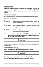
Page 3: ...s personal injury when handling this stone cutter incorrectly CAUTION Thereisapossibilityofpersonalinjuryorpropertydamagewhen handling this stone cutter incorrectly Note In some situations failing to observe WARNING notes could result in d e a t h o r seriouspersonalinjury Besuretoreadandobservethesafetynotestoensure safe and correct use of the stone cutter CAUTION Thefollowingareimportantnotesfor...

Page 4: ...l Donotuse thetoolforpurposesitisnotdesignedfor forexample donotusestonecutterfor cutting tree limbs or logs 8 Dress properly Donotwearlooseclothingorjewelry Itemssuchasthesecanbecaughtinmoving parts Rubberglovesandnon skidfootweararerecommendedwhenworkingoutdoors Wear protective hair covering to contain long hair 9 Use safety equipment Always wear safety glasses and if necessary a face shield dus...

Page 5: ...agedshouldbecarefully checkedtodeterminethatitwilloperateproperlyandperformitsintendedfunction Check for alignment of moving parts breakage of parts mounting and any other conditionsthatmayaffectitsoperation Aguardorotherpartthatisdamagedshould be properly repaired or replaced by an authorized service center unless otherwise indicatedelsewhereinthisinstructionmanual Havedefectiveswitchesreplacedby...

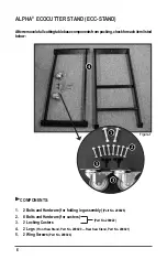
Page 6: ...ssembly Part No 200026 2 8 Bolts and Hardware for casters 3 2 Locking Casters 4 2 Legs Front Saw Stand Part No 200020 Rear Saw Stand Part No 200021 5 2 Wing Screws Part No 200024 Afterremovalofallcuttingtablebasecomponentsfrompacking checkforeachitemlisted below Figure 1 Part No 200022 ...

Page 7: ...10mm wrench 1 Position the two legs to create a scissor configuration as shown in Figure 2 Figure 2 2 Turn assembly on its side and align the holes located at the center of each leg Insert one of the two large bolts Part No 200026 using a flat washer on each side followed by the nylon insert lock nut as shown in Figure 3 and Figure 4 Figure 3 Nylon Lock Nut Figure 4 ...

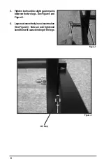
Page 8: ...ts until a slight gap remains between the two legs See Figure 5 and Figure 6 4 Legsmustmovefreelyinascissormotion See Figure 6 Note an over tightened condition will cause binding of the legs Figure 5 Figure 6 Air Gap ...

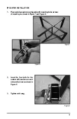
Page 9: ...ncastermountingplatewithmountingholesonbase of stand leg as shown in Figure 7 and Figure 8 2 Insert the four bolts for the casters with washers on each side and lock nut as shown in Figure 9 3 Tighten until snug Figure 7 Figure 8 Figure 9 ...

Page 10: ...rcompleteassembled base stand in the opened position 6 SeeFigure12forcompleteassembled basestandinthefoldedpositionused for transport 4 Repeat process for second caster as shown in Figure 10 Figure 10 Figure 11 Figure 12 ...

Page 11: ...ATIC ECC STAND DRAWING NO PART NO DESCRIPTION QUANTITY 1 200020 Front Saw Stand 1 2 200021 Rear Saw Stand 1 3 200022 Wheel Brake Assembly 1 4 200026 Saw Stand Screw Set 1 5 200024 Wing Screw 2 pc set 1 200023 Saw Stand Assembly ALL ...

Page 12: ...TS 1 Assembled Table Part No 200013 2 Angle Guide Assembly Part No 200018 3 Rip Guide Assembly Part No 200017 4 Hose Holder Assembly Part No 200001 5 Universal Wrench Part No 200019 6 Brush Part No 200025 Figure 13 CAUTION WHEN REMOVING ECOCUTTER TABLE FROM CARTON DO NOT LIFT BY RAIL TUBE ALWAYS USE SIDE HANDLE See page 13 for details ...

Page 13: ...13 INSTRUCTIONS ON REMOVING THE ECOCUTTER TABLE FROM BOX Step 1 Step 2 Figure 14 Figure 15 Figure 16 Step 3 RECOMMENDED METHOD ...

Page 14: ...DED METHODS Please note the following illustrations carefully before assembling table to stand DO NOT LIFT TABLE BY RAIL TUBE TABLE WILL BE DAMAGED IF HANDLED IMPROPERLY INSTRUCTIONS ON HANDLING THE ECOCUTTER TABLE Figure 17 ...

Page 15: ...15 RECOMMENDED METHOD Step 1 Step 2 Figure 18 Figure 19 ...

Page 16: ...16 Step 3 Step 4 RECOMMENDED METHOD Figure 20 Figure 21 ...

Page 17: ...17 ASSEMBLING TABLE TO STAND 1 Place stand in open position SetcasterwheellockstothelockedpositionbypressinglatchdownasshowninFigure 22 and Figure 23 Figure 22 Locked Position Figure 23 ...

Page 18: ...18 Wing Screw Clearance Hole Location Pins Stand Figure 26 2 Pick up table by sides and place on stand Figure 24 Figure 25 Follow the recommended steps on pages 15 and 16 ...

Page 19: ...desofthestand as shown in Figure 27 Figure 27 Location Pins Side Extension Support Slider Tube 4 Alignwingscrewclearanceholewith threadedholeoftablecrosssupport See Figure 28 5 Insert and tighten wing screw to a hand tight condition as shown in Figure 29 6 Repeat process for opposite side to complete the stand assembly Figure 28 Figure 29 ...

Page 20: ...sitionandalignthehoseholdertothesawbaseasshowninFigure30 makingnote of the threaded hole locations Saw Base Threaded Holes Hose Holder Figure 30 Figure 31 2 Install supplied phillips screw and washer and hand tighten with screw driver as shown in Figure 31 ...

Page 21: ...nderside of the saw base as shown in Figure 32 4 Install supplied washer lock washer and wing nut as shown in Figure 33 5 Position hose holder at 90 degrees to the sawbaseandhandtightenwingnuttolock in position Figure 32 Figure 33 Figure 34 ...

Page 22: ...22 INSTALLATION OF THE ANGLE AND RIP GUIDES Angle Guide Rip Guide Ruler Stopper Figure 36 1 Angle and Rip Guides will mount to Ruler Stopper Figure 35 ...

Page 23: ...frulerstopperandthentightenthumb nail screws to secure when in the correct position Figure 38 Figure 39 Figure 37 Figure 40 Example of mounted Angle and Rip Guides for cutting diagonally across a tile Rip Guide Angle Guide Ruler Stopper Figure 41 ...

Page 24: ...24 ALPHA ECOCUTTER TABLE SCHEMATIC ECC TABLE ...

Page 25: ...07 Solid Rail Tube Assembly 1 8 200008 Rail Holder Assembly 1 9 200009 Carry Handle Assembly 1 10 200010 End Seal Plate Assembly 1 11 200011 Removable Ruler Stopper Assembly 1 12 200012 Removable Filler Assembly 1 13 200013 Assembled Table 1 14 200014 Rubber Mat Set 1 15 200015 Side Extension Support Slider TubeAssembly 1 16 200016 Side Extension Support Assembly 1 17 200017 Rip Guide Assembly 1 1...

Page 26: ...ingscrewon the depth indicator of theEcocutterandraise to the highest level as shown in Figure 43 3 Hand tighten wing screwatthisposition INSTALLATION OF ECOCUTTER TO SAW BASE CLAMPS Saw Base Blade clearance slot Wing Screw Clamp Assembly Figure 42 Figure 43 ...

Page 27: ...27 4 Place and position the Ecocutter within the clamp bases as shown in Figure 44 Figure 44 Figure 45 5 PlaceeachofthefourclampassembliesovertheEcocutterbaseandtightenasshown in Figure 45 ...

Page 28: ...cocutter Part No ECC 125 7 Saw Base Part No 200003 1 Usingsuppliedhardware screwstabilizerbasetosawbaseasshowninFigure 46 2 Using supplied bolt screw top portion of stabilizer to Ecocutter Note Leave stabilizer bracket screw and wing nut loose at this time STABILIZER Figure 46 Stablizer Assembly Part No 200002 ...

Page 29: ...de segments just touches rubber table pad See Figure 48 BLADE HEIGHT ADJUSTMENT Ecocutterbladeheightmustbeproperlyadjustedforcuttingdepthbeforeuse Thefollowing steps will ensure proper operation during cutting Note Incorrectbladeheightadjustmentwillresultindamagetothebladeandsawbase Figure 47 Figure 48 Wing Screw ...

Page 30: ...30 3 Tightenwingnuttoahandtight condition See Figure 49 4 Tighten stabilizer bracket bolt with wrench to a snug condition See Figure 50 Figure 50 Figure 49 ...

Page 31: ...e lock wing screw which is located at the front right of the carriage assembly See Figure 51 6 Slidecarriageassembly in a back and forth motiontoassuresmooth operation as shown in Figure 52 Figure 52 Figure 51 Wing Screw ...

Page 32: ...erial 1 Locate the two lock knobs located on the underside of the table See Figure 54 3 Loosen these knobs and pull the side extension support outward towards desired location as shown See Figure 53 4 Re tighten the lock knobs to a hand tight condition Side Extension Support Lock Knob Figure 53 Figure 54 ...

Page 33: ...iththe dust gate in the upright position as shown in Figure 55 2 Slide the dust hose onto the assembly as shown in Figure 56 3 Checkforatightconnectionasshown in Figure 57 4 Routethedusthoseandpowercordthrough the hose holder as shown in Figure 58 Dust Hose Dust Gate Figure 55 Figure 56 Figure 57 Figure 58 ...

Page 34: ...5 Slip the dust bag over hose end as shown in Figure 59 6 Secure with hook and loop strap as shown as in Figure 60 7 See Figure 61 for completed Dust Bag installation Dust bag Figure 59 Figure 60 Figure 61 ...

Page 35: ...35 8 Use supplied hook and loop straps Part No 133551 to secure power cord to dust hose and dust hose to hoseholder See Figure 62 Figure 62 Power Cord Hook and Loop Strap Hook and Loop Strap Dust Hose ...

Page 36: ... 5 6 7 8 9 10 11 12 13 14 15 16 17 18 19 20 21 22 23 24 25 26 27 28 29 30 31 33 38 37 36 35 34 32 39 40 42 43 44 45 46 47 48 45 50 51 52 44 63 45 44 60 59 58 57 31 56 55 45 66 64 80 79 67 68 69 70 78 77 76 75 74 87 88 89 90 90 93 86 87 92 91 82 83 84 85 97 3 96 65 95 98 73 71 72 2 98 81 99 100 ...

Page 37: ...003 Rear Motor Housing Blue 1 13 133041 Cable Clip 2 14 133044 Rubber Switch Cover 1 15 133043 Switch With Screw 1 16 133392 Condenser Assembly 1 17 133029 Self tapping Screw 4 8 65 2 18 133028 Bearing Sleeve 1 19 133078 Handle for ECC 125 1 20 133050 Woodruff Key 1 21 133051 Snap Ring M8 1 22 133030 Air Bridge 1 23 133025 Bearing 608 2RZ 1 24 133024 Insulation Disc 1 25 133439 133012 Armature 110...

Page 38: ...n 1 44 133502 Felt Rings D19xD12xT2 3 45 133492 Bearing 698 2RS 4 46 133498 Spacer D12xd8 5x4T 1 47 133511 Knob Bolt 1 48 133500 Bearing Housing 1 50 133508 Outer Belt 1 51 133488 Pulley Outside 24mm OD RHT 1 52 133495 Fan 1 55 133496 Fan Shaft 1 56 133486 Housing Adapter 1 57 133483 Main Housing 1 58 801086 Side Handle for AWS 125 ECC 125 1 59 133522 Screws M4x15 5 60 133490 Pulley Inside 18mm OD...

Page 39: ... 1 84 133518 Flange Outer for ECC 125 1 85 133516 Flange Inner for ECC 125 1 86 133071 Flat Washer M6 1 87 133084 Wing Screw 3 88 133269 Washer For Ruler 2 89 133528 Guide Pin 1 90 130798 Retaining Rings E 1 91 133527 TT Ruler Guide for ECC 125 1 92 133523 Base Plate Assembly 1 93 133072 Spring Washer M6 1 95 133535 Wrench for ECC 125 1 96 133534 Hexagon Ring Spanner 1 97 133369 Felt Strip Set 2 9...

Page 40: ...Copyright 2013 Alpha Professional Tools All rights reserved 103 Bauer Drive Oakland NJ 07436 800 648 7229 Fax 800 286 0114 www alpha tools com 02 28 2013 ...

Reviews: