background image

Part No:  VSP-110 / VSP-220 

Alpha

®

 Variable

Speed Polisher

Instruction Manual

MANUAL

103 Bauer Drive, Oakland, NJ 07436 • 800-648-7229 • Fax: 800-286-0114

www.alpha-tools.com

Summary of Contents for VSP-110

Page 1: ...Part No VSP 110 VSP 220 Alpha Variable Speed Polisher Instruction Manual MANUAL 103 Bauer Drive Oakland NJ 07436 800 648 7229 Fax 800 286 0114 www alpha tools com...

Page 2: ...On and Off 11 Ground Fault Circuit Interrupter GFCI 12 Testing In line GFCI Unit 12 Variable Speed Adjustment 13 Water Control Valve 13 Side Handle Installation 14 Backer Pad and Other Approved Spindl...

Page 3: ...ty of personal injury or property damage when handling this polisher incorrectly Note In some situations failing to observe WARNING notes could result in death or serious personal injury Be sure to re...

Page 4: ...ing tree limbs or logs 8 Dress properly Do not wear loose clothing or jewelry Items such as these can be caught in moving parts Rubber gloves and non skid footwear are recommended when working outdoor...

Page 5: ...ction Check for alignment of moving parts breakage of parts mounting and any other conditions that may affect its operation A guard or other part that is damaged should be properly repaired or replace...

Page 6: ...at start up Failure to do so may cause an injury due to high impact at initial start up 4 Stop using the polisher immediately when noticing any malfunctions or any suspicious abnormal noises Turn the...

Page 7: ...st and you may hurt yourself 13 Be careful of your surroundings when working in high places When working in high places make sure there are no people below Do not to trap the power supply cord on anyt...

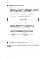
Page 8: ...when it is used on metal plates steel frames or platens Never attach a damaged extension cord to the polisher Note Use the appropriate extension cord as referred below The table shown below is for 11...

Page 9: ...alve SPECIFICATIONS Working Power Supply Single phase AC 50 60 Hz Voltage 110V 220V Plug Type A 110V C 220V Amperage 7 8A 3 9A Wattage 800W Motor Single phase No Load 1600 2800 R P M Polishing Disc Si...

Page 10: ...10 Accessories STANDARD ACCESSORIES 1 Side Handle 2 Wrench 3 Spare Set of Carbon Brushes...

Page 11: ...ltage available at the power outlet Do not use polisher with voltage higher than specified on the name plate 2 Make sure the ON OFF switch is in the OFF position Switching ON AND OFF Switching on Push...

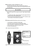
Page 12: ...wer supply and press the GFCI reset button The polisher is ready to start working once the reset button is pressed down Testing In line GFCI Unit Before Each Use Of The Polisher 1 Connect polisher to...

Page 13: ...l numbers are for reference point of mo tor speed 1 is 1 600 RPM and 6 is 2 800RPM INCREASE SPEED DECREASE SPEED Water Control Valve This polisher is equipped with a center water feed system Water flo...

Page 14: ...both side screws from center handle as shown in Figure 8 Pull handle forward and clear of polisher as shown in Figure 9 STEP 2 STEP 3 Thread side handle into either the left or right side of the polis...

Page 15: ...ew the attachment onto the spindle by hand as shown in Figure 11 2 Tighten with supplied wrench as shown in Figure 12 NOTE If attachment does not thread on freely check threads on both surfaces for da...

Page 16: ...and drain center water feed system periodic Carbon brushes wear out over time base on the polisher usage If a carbon brush is worn out it may cause the motor to malfunction or fail to run Whenever the...

Page 17: ...Carbon Brush Replacement 1 Gently pull water tube away from holder as shown in Figure 14 2 Release tube from holder as shown in Figure 15 3 Unwrap 3 inches of coiled harness as shown in Figure 16 Figu...

Page 18: ...18 Figure 17 Figure 18 Figure 19 4 Remove 2 screws from valve bracket as shown in Figure 17 5 Pullvalveassemblyawayfrommount as shown in Figure 18 6 Remove rear case screw as shown in Figure 19...

Page 19: ...h the other hand as shown in Figure 20 NOTE Do not twist case in a side to side motion when pulling back 8 Pull back rear case until carbon brush assembly is exposed as shown in Figure 21 NOTE Do not...

Page 20: ...20 9 Lift spring from carbon brush and place on the side of the brush holder as shown in Figure 23 Figure 23 Carbon Brush Carbon Brush Holder Carbon Brush Wire Spring Figure 22...

Page 21: ...e 24 11 Remove carbon brush from holder as shown in Figure 25 NOTE Each polisher has 2 carbon brushes located on opposite sides of each other After the replacement of the two brushes assemble the poli...

Page 22: ...22 Alpha VSP 110 schematic...

Page 23: ...210012 Thrust Bearing 15x28x6 1 13 210013 Bearing Clamp 1 14 210014 Spring Washer 5 4 15 210015 Screw M5x14 4 16 210016 Gear 1 17 210017 Wave Spring Lock Washer 10 1 18 210018 Circlip for Shaft 10 1 1...

Page 24: ...045 Data Label 1 46 210046 Carbon Brush Holder 2 47 210047 Coil Spring 2 48 210048 210083 Carbon brush 110V PM825 220V 105S 2 49 210049 Screw ST2 9x8 2 50 210050 Inductor For 220V version only 2 51 21...

Page 25: ...authorized signature is required for the credit card being used A second signature is required as an agreement of the overall policy Need More Information For information on Alpha Professional Tools...

Page 26: ...CE Marking 2005 Oakland New Jersey USA Nao Takahashi President September 2005 Limited Warranty of Alpha Wet Polisher Alpha Professional Tools warrants this product against defects in material and work...

Page 27: ..._____________State ________Zip ________________ Telephone ___________________________________________________ Purchase Date _______________________________________________ Dealer s Name ______________...

Page 28: ...Copyright 2005 Alpha Professional Tools All rights reserved 103 Bauer Drive Oakland NJ 07436 800 648 7229 Fax 800 286 0114 www alpha tools com Assembled in China Last revised 11 2005...

Reviews: