0120011-J0 Rev J
32
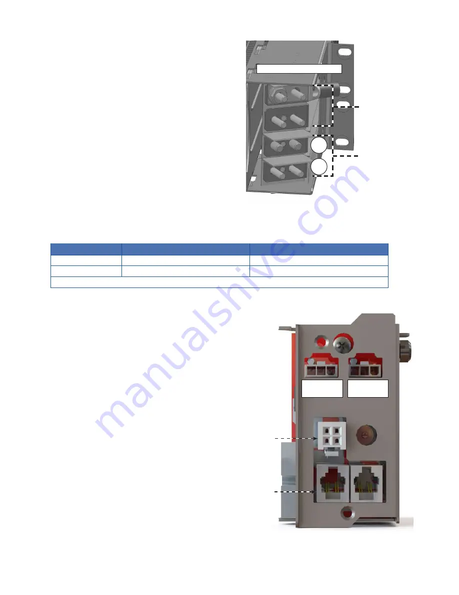
Each shelf has two negative inputs, A and B and two
connections to a positive common input. Half the converters
are powered by feed A and half by feed B as listed in the
following table.
Alpha recommends that each converter shelf have two
dedicated input feeder breakers, if both A and B feeds are
used.
Refer to the specifications in Section 3 on page 12 for
recommended breaker and cable sizes
.
Local electrical
codes have precedence.
2x isolated DC In
inputs
2x common
connections for
positive ground
1/4" holes on 5/8” centers
B
A
Figure 24 — DC input wiring connections
Table B — DC input wiring connections
Shelf width
Feed A to Converter Slots
Feed B to Converter Slots
19"
1-5*
6-9*
23"
1-6*
7-12*
*Slots are numbered from left to right when viewed from the front.
Figure 23 — CAN and fan connections on the shelf interface panel (for reference only)
6�5�6 Making CAN Bus Connections
Each module communicates with the controller using CAN
protocol. The modules report alarms, converter output volt-
ages, ambient temperature and the location of the module
within a cabinet.
Fan power connector
CAN connectors
Major alarm
relay
Minor alarm
relay


