15
0913000-J0 Rev D
4.3 Cordex System Controller
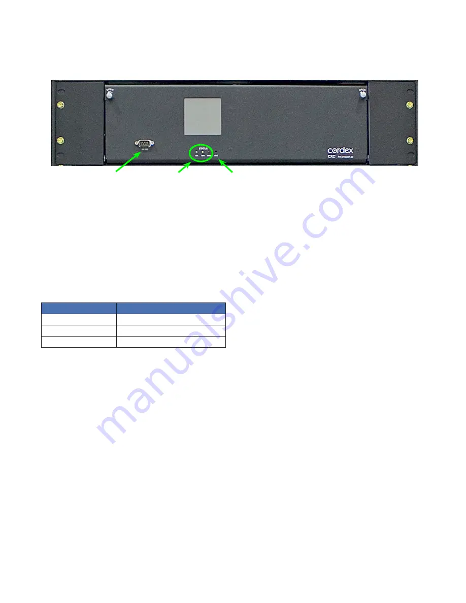
A Cordex system controller, mounted in the primary power section, provides easy access to controls and display
status. The CXC provides comprehensive setup, control, monitoring and communication for Alpha DC power sys-
tems.
Figure 6 — CXCP controller mounted in the power section
4.3.1 Front Panel LEDs
Three LEDs are located on the front panel: one green, one yellow, and one red. These LEDs are used to display the
alarm status of the power system, controller progress and status during startup, and file transfers.
Alarm conditions
Only one LED light is illuminated at a time during alarm conditions. Each LED light corresponds to a specific alarm. A
built-in audio speaker sounds an intermittent tone during active alarms. An LCD message display provides details of
all major and minor alarms.
Illuminated LED
Alarm
Green
OK, no alarms
Yellow
Minor alarm, no Major alarms
Red
Major alarm
Progress and status indication
The LED lights are also used in the following situations:
• Base unit validation—all three LEDs illuminate
• File transfer—red LED illuminates
4.3.2 Front Panel Reset Button
Use the controller LCD to select the RESET menu item before pressing the reset button. Refer to the software manu-
al for details.
Pressing the reset button, on the front panel, restarts the CXC microprocessor. It takes approximately 15 seconds
before the display reappears after pressing the reset button (Figure 6).
4.3.3 Programmable Alarms
In addition to preset major and minor alarms, specific alarms can be configured through a programmable algorithm.
An LCD message display provides details of all major and minor alarms.
See the CXC Installation and Software Manual, shipped with your order, for detailed information.
LEDs
Reset button
Serial port


