1. INTRODUCTION
12
1.5
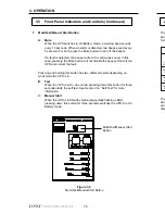
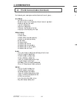
Nexsys UPS Rear Panel (Continued)
Figure 1.2
Rear Panel
External Battery
Pack Cord
AC Input
Circuit Breaker
AC Output
Receptacles
Cooling fans
External Battery
Pack (EBP)
Connector
Communication/Alarm
Interface Connector
External
Battery
Connector
(UPS)
AC Line Cord
Connector
Nameplate
Label
5. MAINTENANCE
49
5.1
Maintenance
The electronic components used in the UPS require no maintenance. If the
unit fails to perform a specific function, refer to the troubleshooting section.
The guide lists typical symptoms, causes, and solutions to problems, starting
with the most obvious and working systematically through the unit.
By following the guidelines contained in this manual, your UPS will continue to
provide years of trouble-free service.
The maintenance–free batteries used in the UPS will be affected by many
variables including operating temperature, number of discharges over the life
of the battery, charging characteristics, and low voltage cell cutoff. The Nexsys
UPS complies with all factory recommendations for charging and discharging
batteries to ensure optimum performance and the longest possible battery life.
During normal operation, the UPS batteries will tend to increase in capacity
over the first three to twelve months of service. After the first ten to fifteen
battery discharges, the available backup power may increase by 20%. Once
the batteries reach this peak, they will slowly lose capacity and, eventually, will
be unable to provide the required backup power.
To determine the maximum amount of battery run time available, run this test
at least once a year. The length of the test varies from several minutes to
many hours and should not be done while critical loads are running, depending
on the UPS's output. This test discharges the batteries, so backup power may
not be available during a utility power failure.
Procedure:
1.
Unplug the AC line cord from the wall receptacle. The front panel On
Battery LED comes on. Record this start time.
2.
Record the time when the Low Battery warning LED starts to flash and
subtract the start time. This is the backup time available. The test can
be interrupted here by plugging the AC line cord back into the wall
receptacle.
CAUTION: The next step shuts down the UPS.
3.
Allow the UPS to continue to a complete shutdown. Record the time
when the UPS goes into the shutdown state with the LEDs flashing
sequentially. Subtract this time from the Low Battery
warning time to
determine the available reserve time.
4.
Switch off the UPS and the load(s). Plug the AC line cord back into the
wall receptacle and start the UPS. The batteries will begin recharging.
5.2
Run-time Testing


