21
2. INSTALLATION
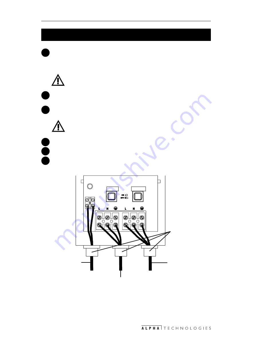
2.4 Wiring the UPS
Locate the output terminals of the host equipment. Remove the supply wires
from the equipment and route them to the UPS's input terminal block. Do not
connect these wires.
NOTE: Any heater wiring in the host equipment should not receive its
power from the UPS since this can cause a system failure.
Route and connect the wires from the UPS's output terminal block to the input
terminals of the load(s).
If used, connect the RS–232 terminal to the host's computer (Section 4.1).
NOTE: Do not run the RS–232 wiring in the same conduits as the AC
wiring.
Connect the line power wires to the UPS's input terminal block.
See all AC connections are secure and correct.
Start and test the UPS (Section 3.2).
3
4
5
6
7
2
INPUT
OUTPUT
Three, 1/2 inch
conduit connectors.
P1250 Output. Use a
minimum of #14
AWG wire.
Line power to P1250
input terminal block.
Use a minimum of
#14 AWG wire.
Wires to external
alarm panel. If
required, use #18
AWG wire.
Figure 2.10
P1250 Wiring Diagram


