background image

43

4.  COMMUNICATION

4.1 RS–232 Interface Port

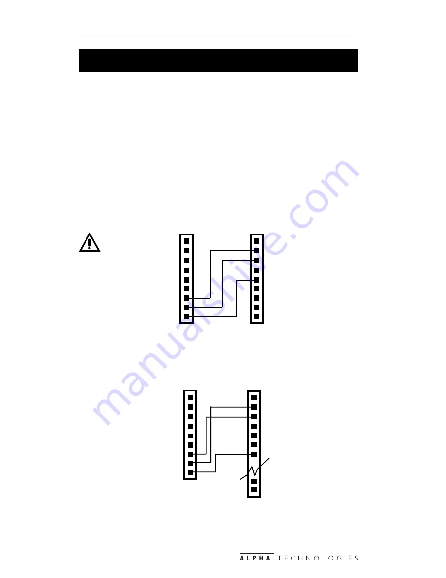
4.1.1 Wiring (Figures 4.1, 4.2)

Alpha Technologies offers a cable for connecting a PC’s RS–232 port to the UPS’s
serial interface.

PINS 1 to 6 are not connected. PIN 7: Tx, RS–232 Transmit. PIN 8: Rx, RS–232
Receive. PIN 9: GND, RS–232 Logic GND.

PURPOSE: Describes the wiring and software setup for
the RS–232 communications port

When the UPS's DE–9 female connector is linked to a PC with Windows 3.1, 95/
98, or terminal emulation software, it can be monitored, controlled and calibrated
with RS–232 ASCII commands.

Figure 4.1

RS–232  9–Pin Serial Cable Connector

2 RXD

3 TXD

UPS RS-232

Serial Connector

9–Pin IBM

PC Serial

Port

1

4

5 GND
6
7
8
9

1

2
3

4
5

6

TXD 7

RXD 8

GND 9

NOTE: Use only
fully shielded
cables to wire
any of the DE–9
connections.

Figure 4.2

RS–232  25–Pin Serial Cable Connector

25–Pin

IBM PC Serial Port

UPS RS–232

Serial Connector

1

3 RXD

2 TXD

4
5
6
7 GND

24
25

1
2
3
4
5
6

TXD 7

RXD 8

GND 9

Summary of Contents for Novus 1250T

Page 1: ...Operator s Manual Novus P1250 and 1250T U N I N T E R R U P T I B L E P O W E R S U P P L I E S From Alpha Technologies ...

Page 2: ...oughout this manual Where they appear servicing should be done only by qualifiedpersonnel A DANGEROUS VOLTAGE exists in this area Use extreme caution ATTENTION important operating instructions Follow them closely i THE ALPHA NOVUS P1250 AND 1250T SAVE THESE INSTRUCTIONS This manual contains important installation and operating instructions Keep it in a safe place CAUTION RISK OF ELECTRICAL SHOCK ...

Page 3: ... voltage and current requirements of the equipment to be protected Do the same for the line voltage and current input into the UPS The UPS should be installed on a dedicated circuit breaker equippedline Alert fire emergency and service personnel a UPS is installed by placing a warning label on the electrical panel and the host equip ment When connecting a load make sure it does not draw more power...

Page 4: ... required precautions When not in service charge the batteries once every three months for optimum performance and long life Batteries should be inspected yearly for signs of cracks leaks or swelling Always replace batteries with those of identical type and rating Never install old or untested batteries Proper disposal is required Refer to local codes for procedures DANGER Batteries may explode if...

Page 5: ...cing the batteries or the UPS Do not lay tools on top of the batteries Do not let live battery wires touch the UPS s chassis Shorted wires can cause a fire or explosion Wear insulated gloves and eye protection when servicing the batteries Switch the battery circuit breaker OFF before connecting or discon necting the batteries DANGER Lead acid batteries generate Hydrogen gas a potential fire hazard...

Page 6: ...re and shock hazards do not expose this UPS to rain or moisture WARNING Never run the UPS at more than 100 of output power Section 3 6 3 Overloading can damage the inverter the batteries or the control electronics PROCEDURE TurnOFF All loads The battery input output and line circuit breakers 1 Mount the UPS Section 2 1 and 2 2 or 2 3 Connect the UPS Section 2 4 Start and test the UPS Section 3 2 3...

Page 7: ...isconnected but power will still be present at the UPS s output To prevent injury to service or emergency personnel always turn the battery circuit breaker OFF 1 5 Switch the battery circuit breaker OFF Switch the input circuit breaker on the terminal block OFF Switch the input circuit breaker on the terminal block OFF 3 2 4 Turn the line circuit breaker OFF ...

Page 8: ... Quick Reference Guide 24 3 2 Starting and Testing the UPS 26 3 3 Shutting Down the UPS 27 3 4 Self Test 28 3 5 Troubleshooting 29 3 6 Front Panel Indicators and Controls 33 3 6 1 On Line and On Battery LED s 34 3 6 2 Low Battery LED 35 3 6 3 Percentage Power Indicator 36 3 6 4 Battery Charge Indicator 37 3 6 5 Test Manual Start Button 38 3 6 5 1 Test Button 38 3 6 5 2 Manual Start Button 38 3 6 6...

Page 9: ...s 49 4 3 3 Unit Input Output Values 50 4 3 4 Maintenance Specifications 51 4 3 4 1 Password Change Procedure 52 4 3 5 Line Slow Detection Set Up 53 4 3 5 1 Parameter Change Procedure 53 4 4 How To Work With Menus 55 5 MAINTENANCE 57 5 1 Run Time Testing 58 5 2 Fan Replacement Procedure 60 5 3 Battery Pack Replacement Procedure 61 5 4 Battery Changing Procedure 62 5 5 Troubleshooting 64 5 6 Return ...

Page 10: ...vusP1250and1250T UninterruptiblePowerSupplies UPS An unpacking checklist Section 1 2 A description of its various panels connections and switches Sections 1 3 A description of the P1250 terminal block Section 1 4 A description of the 1250T terminal block Section 1 5 ...

Page 11: ... floor mounted on a pedestal The pedestal mounting kit is ordered from Alpha Technologies EquipmentProtection Equipment is protected from brownout and surges ServiceFriendly Convenient battery access for quick and easy servicing Load Control on Low Battery Control signal relay contacts for automated equipment shutdown if the UPS is discharged by an extended power outage 1 1 The Alpha Advantage Pur...

Page 12: ...tainer Alpha Technologies is not responsible for damage caused by improper packaging of returned UPSs Read This Operator s Manual Before installation or use become familiar with your UPS by reviewing the procedures and drawings in this manual If you have any questions about safe installation operation or maintenance contact Alpha Technologies Complete the following for your records Model Serial Op...

Page 13: ...cess the interior unlock lift up the front enclosure and move it out of the way A nylon rope and a grounding wire connecting the two halves are at the bottom A lock at the bottom of the front enclosure prevents unauthorized personnel from opening it The keys are shipped in the mounting kit DANGER When mounting the front enclosure onto the rear take great care that the front does not touch the batt...

Page 14: ...able assembly Nexsys PC RS 232 DE 9 Male to DB 25 Female 870 540 22 Cable assembly Nexsys PC RS 232 DE 9 Male to DE 9 Female Battery Connector This connects the batteries to the UPS Temperature Sensor This sensor measures the battery s temperature The charging current is temperature dependent Internal Fan Connector This connects the internal fan to the UPS Batteries They provide the backup power T...

Page 15: ...nsformer s output to the inverter Transformer Line Power Connection This connects line power to the transformer s input BatteryTerminals The batteries are connected in series Conduits These three 1 2 inch conduits connect the UPS to the loads line power and if used to the external alarm panel Conduit or armoured cable is used They can be replaced by 3 4 inch conduits which are not provided by Alph...

Page 16: ...7 1 INTRODUCTION 1 3 A Tour of the Alpha P1250 and 1250T Figure 1 2 Shelf 1250T Version Shown 10 4 5 3 2 7 8 9 12 16 1 11 13 16 15 6 10 14 ...

Page 17: ... caused by lightning strikes A second suppressor can be attached to the load side as an ordered option Input Terminal Block This terminal block connects the P1250 to line power Line Power Circuit Breaker This circuit breaker connects or disconnects the P1250 from line power It must be ON for normal operation Output Terminal Block This terminal block connects the loads to the P1250 s output OutputP...

Page 18: ...ontacts in the terminal block Service Alarm When the Display and Control panel displays a fault this alarm is activated Low Battery Alarm When the battery voltage is below 44 volts this alarm is activated On Battery Alarm When the UPS is operating on battery power this alarm is activated Self Test The self test starts when this input is shorted 1 1 5 1250T Terminal Block TB1 TB2 Microprocessor P12...

Page 19: ...al block connects the 1250T to line power InputCircuitBreaker This circuit breaker connects or disconnects the 1250T from line power It must be ON for normal operation OutputTerminalBlocks These four terminal blocks connect the loads to the 1250T s output power OutputCircuitBreakers These four circuit breakers connect or disconnect the loads from the P1250 s power They must be ON for normal operat...

Page 20: ...1 6 External Alarm Terminal Block Wiring Diagram On Battery To start the self test short these contacts The user provides the switch Service Alarm Low Battery Warning TB1 TB2 TB3 TB4 TB5 TB6 TB7 TB8 Microprocessor 1250T Interior Contacts close on alarm ...

Page 21: ...onTwo Installation This section tells you how to install and wire the UPS A pre installation checklist Section 2 1 How to wall mount Section 2 2 How to pedestal mount Section 2 3 How to wire the UPS Section 2 4 ...

Page 22: ...may have inadequate electrical grounding A qualified electrician should inspect it before installation Stand by Generators The UPS has frequency sense and synchronization circuits for connection to most generators Before installation compare the generator s output voltage and frequency to the UPS s input requirements as listed on their nameplates As a safety margin use a generator which produces t...

Page 23: ...weather protection in normal operating conditions Where there is a risk of snow buildup or flooding mount the UPS as high as possible The mounting location must be sheltered from road splash Ensure the two bolts can be tightened from inside the host Make sure wiring is not damaged and the bolts don t touch moving parts Place the mounting bracket on the host and make scribe marks for the two mounti...

Page 24: ...the mounting bracket Figure 2 3 Mounting the UPS on the Bracket DANGER Turn the battery breaker OFF The UPS supplies lethal power levels without being hooked up to utility line power Unlock and open the enclosure Disconnect both the grounding wire and the nylon rope and set the front aside Remove the two knockouts for the 5 16 inch bolts at the top of the rear enclosure Mount the rear enclosure on...

Page 25: ...inch bolt Install conduits and wires for connecting the UPS to the host s electrical connections Figure 2 4 Attaching the UPS to the Bracket 5 6 4 STEP 3 Connecting the UPS Connect the UPS Section 2 4 Start and test the UPS Section 3 2 Connect the nylon rope and the ground wire to the front enclosure Attach the front enclosure to the rear enclosure 1 4 3 2 ...

Page 26: ...s weather protection in normal operating conditions Where there is a risk of snow buildup or flooding mount the UPS as high as possible The mounting location must be sheltered from road splash DANGER Read the safety instructions in the introduction of this manual Figure 2 5 Pedestal Mounting Bracket Top View STEP 1 Attach the Mounting Bracket to the Concrete Slab Procedure Use the mounting bracket...

Page 27: ...e battery breaker OFF The UPS supplies lethal power levels without being hooked up to line power Unlock and open the enclosure There are two connections between the enclosure halves a grounding wire and a nylon rope Disconnect both and then set the enclosure front aside Mount the rear enclosure to the pedestal mount s rear Connect the two parts together with the three 1 4 inch screws in the mounti...

Page 28: ...the rear with the two attachment screws Connect the UPS Section 2 4 Start and test the UPS Section 3 2 Connect the nylon rope and the ground wire on the rear enclosure to the front enclosure Attach the front enclosure to the rear enclosure Figure 2 8 UPS Mounted on the Pedestal STEP 3 Connecting the UPS 1 4 5 3 2 ...

Page 29: ... not touch the battery terminals DANGER PURPOSE Describes how to connect the UPS to the loads the external alarm panel and to line power Figures 2 10 2 11 Wiring Checklist Use only copper wire For details of wiring the P1250 see Figure 2 10 For details of wiring the 1250T see Figure 2 11 Make the connections with either conduit or armoured cable If the installer finds the 1 2 inch conduits too sma...

Page 30: ...block to the input terminals of the load s If used connect the RS 232 terminal to the host s computer Section 4 1 NOTE Do not run the RS 232 wiring in the same conduits as the AC wiring Connect the line power wires to the UPS s input terminal block See all AC connections are secure and correct Start and test the UPS Section 3 2 3 4 5 6 7 2 INPUT OUTPUT Three 1 2 inch conduit connectors P1250 Outpu...

Page 31: ... Figure 2 11 1250T Wiring Diagram Wires to external alarm panel If required use 18 AWG wire 1250T output Use 18 to 16 AWG wire Three 1 2 inch conduit connectors Utility line power to 1250T input terminal block Use a minimum of 14 AWG wire ...

Page 32: ...d operate the UPS The UPS s operating modes Section 3 1 Starting and testing procedures Section 3 2 Shut down procedures Section 3 3 Self test procedures Section 3 4 Troubleshooting procedures Section 3 5 Operating procedures for the Control and Display Panel Section 3 6 ...

Page 33: ... 6 1 ONBATTERY The UPS automatically switches into this mode when line voltage is outside preset values or the Manual Start button is pressed when it is in Standby mode Section 3 6 1 BOOST The UPS automatically switches into this mode when line voltage drops below a preset limit Section 3 6 1 STANDBY The LEDs are sequentially flashing The UPS is not providing power to the loads but its electronics...

Page 34: ...GENERATOR This changes the UPS s internal parameters from normal to generator This broadens its parameters to accommodate voltage fluctuations when a generator is used as a backup power source Section 3 6 8 If the UPS switches back and forth from On Line to On Battery modes because of a noisy utility line changing the parameters from Normal to Generator may stop this When the Fault 110 LED is ON t...

Page 35: ...breaker This tests the UPS s ability to transfer to battery power The On Battery LED turns ON Turn ON the input circuit breaker The On Line LED turns ON 1 2 PURPOSE Describes how to start and test the UPS after installation or maintenance STEP 2 Start the UPS 1250T Model Shown P1250 is the same Turn ON the battery circuit breaker The LEDs sequentially flash Section 3 6 6 Turn ON the input circuit ...

Page 36: ...much power is drawn Section 3 6 3 WARNING Never operate the UPS when the 110 LED is ON Overloading will damage it 1 2 2 PURPOSE Describes how to shut down the UPS during normal operations The emergency shutdown procedure is on the inside rear cover Procedure 1250T Model Shown P1250 is the same Turn OFF the output circuit breaker s Turn OFF the battery circuit breaker Turn OFF the input circuit bre...

Page 37: ...about one minute to run NOTE It should not be done when critical loads are running 7 Sec It returns to the mode it was in before the self test Start Is the On Line 25 LED ON Press down the Test Button for 7 seconds NO YES YES LED ON LED OFF Go To Section 3 5 Does the UPS show abnormal behaviour or is the 110 LED On or Flashing The test runs for about 1 minute Do Not Proceed NO ...

Page 38: ... G N I H S A L F G N I H S A L F G N I H S A L F G N I H S A L F S M R A L A S M R A L A S M R A L A S M R A L A S M R A L A n o i t i d n o C n o i t i d n o C n o i t i d n o C n o i t i d n o C n o i t i d n o C e n i L e n i L e n i L e n i L e n i L y c n e u q e r F L L P L L P L L P L L P L L P d a o l r e v O d a o l r e v O d a o l r e v O d a o l r e v O d a o l r e v O h g i H h g i H h...

Page 39: ...L F G N I H S A L F G N I H S A L F G N I H S A L F S M R A L A S M R A L A S M R A L A S M R A L A S M R A L A n o i t i d n o C n o i t i d n o C n o i t i d n o C n o i t i d n o C n o i t i d n o C e n i L e n i L e n i L e n i L e n i L y c n e u q e r F L L P L L P L L P L L P L L P d a o l r e v O d a o l r e v O d a o l r e v O d a o l r e v O d a o l r e v O h g i H h g i H h g i H h g i ...

Page 40: ...r e v O d a o l r e v O e u l a v d e i f i c e p s a s d e e c x e e g a t t a w t u p t u o s S P U e h T S N O I T I N I F E D M R A L A S N O I T I N I F E D M R A L A S N O I T I N I F E D M R A L A S N O I T I N I F E D M R A L A S N O I T I N I F E D M R A L A e n i L e n i L e n i L e n i L e n i L y c n e u q e r F e c n e r e l o t f o t u o g n i t a u t c u l f s i y c n e u q e r f e ...

Page 41: ... O e d o M y r e t t a B n O t u p t u O t u p t u O t u p t u O t u p t u O t u p t u O e g a t l o V t s e T f l e S t s e T f l e S t s e T f l e S t s e T f l e S t s e T f l e S n o t t u B t u p t u O t u p t u O t u p t u O t u p t u O t u p t u O e g a t l o V t s e T f l e S t s e T f l e S t s e T f l e S t s e T f l e S t s e T f l e S n o t t u B t r o h S t u p t u O h g i H t i u c r...

Page 42: ... Batt and Load buttons are pressed to activate various functions Sections 3 6 1 to 3 6 8 describes how to operate the UPS with this panel PURPOSE Describes how to operate the UPS with the Display and Control Panel Figure 3 4 Figure 3 4 Display and Control Panel Layout On Battery 50 LED Test Button Test 100 LED On Line 25 LED Fault 110 LED Batt Button Load Button Low Battery 75 LED ...

Page 43: ... g n i h s a l F s s e r g o r p n i t s o o b t u o n w o r B n On On On On O g n i h s a l F g n i h s a l F g n i h s a l F g n i h s a l F g n i h s a l F n o r e t r e v n i w o l o o t r o h g i h o o t t u p n I f f O f f O f f O f f O f f O f f O f f O f f O f f O f f O s i r o e d o m n w o d t u h S n i s i S P U e h T f f o d e n r u t Figure 3 5 Display and Control Panel On Line and On...

Page 44: ... on the size of the load For more information on these states see Section 3 7 On Line Mode When flashing it operates normally This should not last more than an hour If it does perform troubleshooting Section 3 5 to see if the UPS has a problem AlmostDischargedBattery On Battery Mode When flashing the battery is almost discharged with only a small amount of backup power left Shut down the loads bef...

Page 45: ...he LEDs become a power meter showing the UPS s approximate power output Press the load button for 1 second Example 75 of maximum outputpower WARNING The UPS can be operated at any value up to 100 but do NOT run it when the 110 LED is ON Overloading can cause reduced runtime unexpected shutdowns or damage to the inverter ...

Page 46: ...tteries that can not reach a full charge should be serviced or replaced Test the runtime annually Section 5 1 to see if they still hold an adequate charge Start The LEDs become a battery meter showing the battery s approxi mate charge Press the Batt button for 1 second Example Batteries are 100 charged 1 Sec ...

Page 47: ...t line power present It automatically switches to On Line mode when it is 2 It is shut down by an RS 232 Output Shutdown command when in On Line or On Battery mode It stays latched in Standby mode until an Output Shutdown Inactive command is sent If line power is available it automatically switches into On Line mode If not it stays in this state until it is 3 6 6 Standby Mode If the LEDs are seque...

Page 48: ... loads running depending on the UPS s backup power 7 Sec 7 Sec Start Is the UPS in On Line or Boost Modes YES Simultaneously press down the Mute and Batt buttons for seven seconds The 110 100 75 50 and 25 LEDs are flashing Replace the battery pack Section 5 3 To exit simultaneously press down the Mute and Batt buttons for seven seconds The LEDs stop flashing 7 Sec 7 Sec NO Do Not Proceed ...

Page 49: ...switched to Generator parameters Start Simultaneously hold down the Mute and Load buttons for seven seconds The 100 Test LED flashes during this proce dure 7 Sec 7 Sec One of the two following combinations of 25 50 and 100 LEDs appear UPS is operating on generator parameters UPS is operating on normal parameters 7 Sec To toggle from one parameter to the other press the Batt button within 30 second...

Page 50: ...lable the On Line LED turns ON line power is provided to the loads and battery charging starts Low Battery Disconnect The UPS automatically switches into this state disconnecting the battery to prevent a deep discharge There is some current leakage so remaining in this state for a long time will result in a short battery life or permanent battery failure All LEDs are OFF indicating it is turned of...

Page 51: ...ou how to remotely monitor and control the UPS with RS 232ASCIIcommands Hardware and software setup of the RS 232 port Section 4 1 Describes the Main Menu Section 4 2 Describes the Sub Menus Section 4 3 Describes how to work with the menus Section 4 4 ...

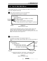
Page 52: ... UPS s DE 9 female connector is linked to a PC with Windows 3 1 95 98 or terminal emulation software it can be monitored controlled and calibrated with RS 232 ASCII commands Figure 4 1 RS 232 9 Pin Serial Cable Connector 2 RXD 3 TXD UPS RS 232 Serial Connector 9 Pin IBM PC Serial Port 1 4 5 GND 6 7 8 9 1 2 3 4 5 6 TXD 7 RXD 8 GND 9 NOTE Use only fully shielded cables to wire any of the DE 9 connec...

Page 53: ... I M R E T E L B A T P U T E S L A N I M R E T E L B A T P U T E S L A N I M R E T E L B A T P U T E S L A N I M R E T E L B A T P U T E S L A N I M R E T e p y T n o i t a l u m E e p y T n o i t a l u m E e p y T n o i t a l u m E e p y T n o i t a l u m E e p y T n o i t a l u m E e l b i t a p m o C r o 0 0 1 T V e d o M x e l p u D e d o M x e l p u D e d o M x e l p u D e d o M x e l p u D e...

Page 54: ...ss Enter Figure 4 5 Main Menu Screen Prompt Sub Menu Numbers AlphaTechnologies Name of Unit 0 Main Menu 1 Unit Specification 2 Input Output Values 3 Maintenance 4 Line Slow Detection Setup Line status Current Status Output status Current Status Faults If any otherwise blank Alarms If any otherwise blank _ PURPOSE Describes the RS 232 main menu Figures 4 6 4 7 4 8 and 4 9 show the messages and desc...

Page 55: ... N I L S U T A T S E N I L S U T A T S E N I L S U T A T S E N I L l a m r o N l a m r o N l a m r o N l a m r o N l a m r o N l a m r o n s i r e w o p e n i L t s o o B t s o o B t s o o B t s o o B t s o o B n o i t a r e p o n i s i e d o m t s o o b e c n e r e l o t f o t u o s i r e w o p e n i L t u o k c a l B t u o k c a l B t u o k c a l B t u o k c a l B t u o k c a l B t n a t s i x e...

Page 56: ... F S Y A L P S I D T L U A F t i u c r i C t r o h S t i u c r i C t r o h S t i u c r i C t r o h S t i u c r i C t r o h S t i u c r i C t r o h S t i u c r i C t r o h S t u p t u O i H _ t u o V i H _ t u o V i H _ t u o V i H _ t u o V i H _ t u o V h g i H e g a t l o V t u p t u O i H _ t a b V i H _ t a b V i H _ t a b V i H _ t a b V i H _ t a b V h g i H e g a t l o V y r e t t a B o L _...

Page 57: ... 301 Battery Test ON OFF 31 Output Shutdown 311 Shutdown ON OFF 32 Inverter ON OFF 320 Set Inverter Off Delay 321 Inverter ON OFF 33 Change Password 4 LINE SLOW DETECTION SETUP 40 Slow Detect High Lmt 41 Slow Detect Low Lmt 42 Slow Detect High Hyst 43 Slow Detect Low Hyst 44 Slow Detect Boost High 45 Slow Detect Boost Low Figure 4 10 RS 232 Menu Tree To access any item from the main menu type its ...

Page 58: ...I t u p n I t u p n I t u p n I e g a t l o V s t l o V X X X e h t g n i r e t n e e g a t l o v e n i l e h T S P U t u p t u O t u p t u O t u p t u O t u p t u O t u p t u O e g a t l o V s t l o V X X X X e g a t l o v t u p t u o e u r t s S P U e h T A V t u p t u O A V t u p t u O A V t u p t u O A V t u p t u O A V t u p t u O A V X X A V t u p t u o e u r t s S P U e h T y r e t t a B y ...

Page 59: ...l o V e g a t l o V e g a t l o V e g a t l o V e g a t l o V s t l o V X X X X e h t t a e g a t l o v S M R e u r t e h T t u p t u o t n e r r u C t n e r r u C t n e r r u C t n e r r u C t n e r r u C s p m A X X e h t t a t n e r r u c S M R e u r t e h T t u p t u o q e r F q e r F q e r F q e r F q e r F z t r e H X X X r e w o p e n i l e h t f o y c n e u q e r f e h T t u p t u o e h t ...

Page 60: ... T U O 1 3 T U P T U O 1 3 N W O D T U H S n a c y a l e d A t u p t u o e h t f f o s t u h s s i h T n r u t o t e m i t r o f r o t a r e p o e h t y b t e s e b n i d e t s u j d a s i y a l e d e h T s d a o l e h t f f o g n i t t e s t l u a f e d a h t i w s p e t s d n o c e s 5 0 s i g n i t t e s m u m i x a m e h T s d n o c e s 0 f o s d n o c e s 0 0 3 r o s p e t s 0 0 6 R E T R E V...

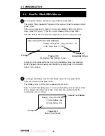
Page 61: ...ssword and press Enter NOTE The password is four numbers numbers only no letters long The words Re enter New Password appears on the screen Retype the new password and press Enter If you retyped in the wrong password the screen displays Error in entering data please try again Type the correct password and press Enter If the retyped password is correct the screen returns to the main menu 1 3 2 ...

Page 62: ...rator back to the Line Slow Detection Screen 1 3 2 Changing these parameters lets the operator customise the UPS s detection and warning values Normally these settings do not have to be changed Figure 4 15 CAUTION Improper parameter values can cause permanent damage and they must only be changed by well trained personnel They are relative numbers that only make sense when viewed through the UPS s ...

Page 63: ... High Increasing this raises the return voltage level from Boost mode to On Line mode 45 Slow Detect Boost Low Increasing this raises the voltage level where the UPS goes to Boost mode 43 Slow Detect Low Hyst Decreasing this lowers the voltage level where the UPS resumes On Line mode after an low line condition has been corrected 41 Slow Detect Low Lmt Increasing this makes the UPS more sensitive ...

Page 64: ...6 Maintenance Menu Screen Prompt 0 MAIN MENU 3 MAINTENANCE 30 Battery Test Options available in Line Mode 31 Output shutdown 32 Inverter On Off available in Standby Mode 33 Change Password can only be changed in Line Mode _ Function Number 2 Type 30 and press Enter The Battery Test Options screen appears Figure 4 17 Numbers or words inside square brackets show the UPS s current status or value Fig...

Page 65: ...value 1 225 _ To change the battery test period type 300 and press Enter The words Enter password appear on the screen Type the password and press Enter If the wrong password is typed in the screen displays Error in entering data please try again Type the correct password and press Enter The Set Battery Test Period screen appears as shown in Figure 4 18 3 4 To Change the Battery Test On Off status...

Page 66: ...ble back up time Section 5 1 How to change the fan Section 5 2 How to change the battery pack Section 5 3 How to change the batteries in the battery pack Section 5 4 How to troubleshoot the UPS Section 5 5 How to return the UPS for servicing Section 5 6 How to order parts Section 5 7 Specifications Section 5 8 ...

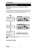
Page 67: ... that depends on the UPS s output PURPOSE Describes how to measure the battery s backup time Available Backup Time Start Time Low Battery Time Start Switch the input circuit breaker OFF The On Battery LED turns ON Record this start time Record the time when the Low Battery LED starts flashing Continued Next Page Start Time Low Battery Time Subtract this time from the start time This is the availab...

Page 68: ...s the available battery reserve time Shutdown Mode Time Switch the input circuit breaker ON Line power is provided to the loads and the battery starts recharging Let the UPS go into shutdown mode LEDs are sequen tially flashing Record the time this happens Available Battery Reserve Time Available Backup Time Shutdown Mode Time ...

Page 69: ...test starts the fan If correctly installed the air blows from the UPS s bottom to top 1 2 3 4 5 PURPOSE Describes how to replace the fan Tools required Phillips screwdriver Procedure Switch the UPS into Hot Swap Mode Section 3 6 7 Squeeze the sides of the fan s connector lock to unlock the power connector Then slide it apart Remove the two fan retaining screws Remove the fan STEP 1 Remove the Old ...

Page 70: ...e caught between the restraining bar rib and the enclosure front causing a short Step 2 Install the new battery pack To install the battery pack slide the tabs on both sides of the pack behind the holding posts on both sides of the terminal block 1 Step 1 Remove the old battery pack Switch the UPS into Hot Swap Mode Section 3 6 7 Turn the battery circuit breaker OFF Slide the battery connector apa...

Page 71: ...OSE Describes how to replace the batteries in the battery tray Figure 5 1 WARNING Make sure the wires are not trapped under the restraining bar Frayed wires can cause shorting 5 4 Battery Changing Procedure Procedure NOTE The tray must be removed from the UPS before starting Step 1 Remove the old batteries Remove the insulating pad covering the batteries Remove the wires connecting the batteries b...

Page 72: ... Battery Wires Attachment Screw Attachment Nut Restraining Bar Batteries Battery Tray Negative Terminal Positive Terminal 2 5 6 4 3 Step 2 Install the new batteries Place the new batteries in the tray Perform numbers 1 to 5 in Step 1 in reverse order The battery tray is ready for installation 1 2 3 ...

Page 73: ...w to troubleshoot the UPS Figure 5 2 The most common problems symptoms and causes are listed in Figure 5 2 It starts off with the simplest problems working to the most complex If the operator can not resolve the problem contact Alpha Technologies Maintenance and troubleshooting should only be done by qualified personnel The UPS s electronics require no maintenance By following the guidelines in th...

Page 74: ... n o t i n r u T e d o m Y R E T T A B N O e d o m Y R E T T A B N O e d o m Y R E T T A B N O e d o m Y R E T T A B N O e d o m Y R E T T A B N O n o e m o c t o n s e o d r e w o p a g n i r u d e r u l i a f e g r a h c y r e t t a b w o L s e i r e t t a b e h t e g r a h C S P U y t l u a F r o d n e V t c a t n o C s s e l s i e m i t p u k c a B s s e l s i e m i t p u k c a B s s e l s i e...

Page 75: ...and insured COD and freight collect cannot be accepted ALPHA TECHNOLOGIES DOES NOT ASSUME RESPONSIBILITY FOR DAMAGE CAUSED BY THE IMPROPER PACKAGING OF RETURNED UNITS 5 6 Return Instructions PURPOSE Describes how to return the UPS for repair To order parts contact the Alpha Technologies Customer Service Department directly at United States 360 647 2360 Canada 604 430 1476 United Kingdom 44 1279 42...

Page 76: ...o n 0 2 1 8 5 2 7 7 1 m o n 0 3 2 c e s m e m i T r e f s n a r T c e s m e m i T r e f s n a r T c e s m e m i T r e f s n a r T c e s m e m i T r e f s n a r T c e s m e m i T r e f s n a r T p y t 4 2 n o i t c e t o r P t u o n w o r B n o i t c e t o r P t u o n w o r B n o i t c e t o r P t u o n w o r B n o i t c e t o r P t u o n w o r B n o i t c e t o r P t u o n w o r B f o 3 8 w o l e ...

Page 77: ... d a o l r e v O y t i c a p a C d a o l r e v O y t i c a p a C d a o l r e v O y t i c a p a C d a o l r e v O y t i c a p a C d a o l r e v O s e t u n i m 3 r o f 0 1 1 B d n o i t a u n e t t A e s i o N B d n o i t a u n e t t A e s i o N B d n o i t a u n e t t A e s i o N B d n o i t a u n e t t A e s i o N B d n o i t a u n e t t A e s i o N e d o M n o m m o C e d o M l a m r o N 0 4 0 6...

Page 78: ... d n o c m m 9 1 g n i t n u o M g n i t n u o M g n i t n u o M g n i t n u o M g n i t n u o M l a t s e d e p r o e l o P g n i l o o C g n i l o o C g n i l o o C g n i l o o C g n i l o o C C D V 8 4 d e l l o r t n o c r o s s e c o r p o r c i M d l e i f d n a e l b a p p a w s t o h h c n i 5 1 3 r e t r e v n I n i g n i t a r e p o n a f e l b a e c a l p e r t n e i b m a l a n r e t n...

Page 79: ...ne thattheunithas beendamaged due tooneof these causes oriftheunitisfree of defects a handling or repair fee may be assessed prior to returning the unit WITH RESPECT TO BATTERIES PERIPHERAL DEVICES ATTACHMENTS OR APPARATUS NOT MANUFACTURED BY ALPHA TECHNOLOGIES ALPHA WILL ASSIGNTOTHEPURCHASERITSRIGHTSUNDERTHEORIGINALMANUFACTURER S WARRANTY OF SUCH BATTERIES PERIPHERAL DEVICES ATTACHMENTS OR APPARA...

Reviews: