Tri Power X33 Mod HP Manual | Rev 1.20 | © Alpha Technologies GmbH 2013
Operating
a
nd Main
tena
nce
Manua
l
Tri Power X33 Mod HP
35
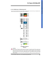
ATTENTION
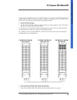
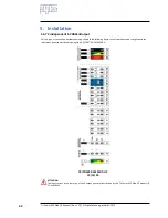
The connection of a Tri Power X33 Mod HP BATTERY to the UPS Tri Power X33 Mod HP 40kVA, 45kVA and 60kVA
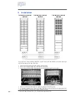
must be done using BOTH cable kits supplied with the Tri Power X33 Mod HP BATTERY
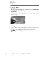
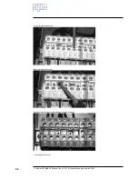
6. in each Tri Power X33 Mod HP BATTERY insert the terminal block securing it with the 2 screws provided;
7. in each Tri Power X33 Mod HP BATTERY secure the lower front panel.
5.2.7 Protection
To ensure correct operation of the UPS and its accessories the electrical system must be adequately protected. Automa-
tic differential switches and thermal circuit breakers are typically used, connected between the mains supply and the
UPS with the purpose of providing additional protection in the event of overloads or short circuits.
INDICATION
Chapter 11 gives information about the thermal circuit breakers.
5.2.8 Earthing
Connect the earth wire leading from the low voltage switchboard panel to the EARTH terminal on the UPS terminal
block.
INDICATION
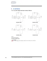
The wiring diagrams are given in the DIAGRAMS chapter.
5.2.9 Connecting the power supply
For safety reasons, connection of the power supply must be the last thing to be done.
Before connecting the power supply cables make sure that the maintenance by-pass S1 is open in the OFF position and
arrange fuses and jumpers on the terminal block according to the required input-output configuration.
INDICATION
Chapter 11 gives
information about sizing cables, fuses, circuit breakers and differentials.
The default configuration for the UPS Tri Power X33 Mod HP units distributed by ALPHA is a THREE-PHASE INPUT and a
THREE-PHASE OUTPUT.
If you are using this type of distribution, the fuses and jumpers are already correctly sized and positioned.
For different configurations please consult the following chapter and wiring diagrams in the DIAGRAMS chapter.
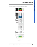
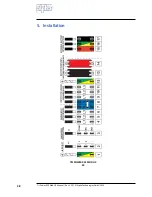
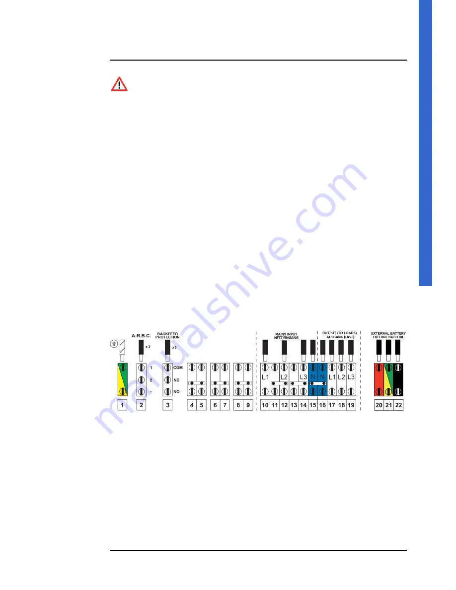
Connect the power cable leading from the low voltage switchboard to the UPS terminals as illustrated in the previous
figure (or in the wiring diagram for the type of connection used), taking care to observe the cyclic direction of the phases
(L1, L2, L3).

