background image

Introduction

The Alpha Telecom UT3620 

NT1 is a 

compact, versatile, and affordable Network 
Termination 1 (NT1) device for connecting 
Terminal Equipment (TE) to the Integrated 
Services Digital Network (ISDN).

This installation guide describes how to install 
the UT3620 for use with Video Conferencing 
Equipment and ISDN Telephones.

Package Contents

One UT3620 

NT1

Three RJ-45 to RJ-45 cables
Three RJ-11 to RJ-45 hybrid cables
Six wire ties for cable management
One power supply (16Watt or 40Watt)
Manual
Warranty Card
Wall-Mounting Kit

Triple 

Triple 

1

UT3620 Triple NT1 Installation Guide

Summary of Contents for UT3620 Triple NT1

Page 1: ...UT3620 Triple NT1 Installation Guide ...

Page 2: ......

Page 3: ...Revision 1 03 8 14 2008 UT3620 Triple NT1 Installation Guide Information in this guide is subject to change without notification ...

Page 4: ...Copyright 2000 2008 Alpha Telecom Inc U S A This document may only be distributed in printed or electronic form by Alpha Telecom or by authorized by Alpha Telecom parties ...

Page 5: ...15 15 15 16 17 19 8 12 Figures Figure 1 UT3620 Perspective View Figure 2 UT3620 Rear Panel Figure 3 Interface Wiring Diagram Figure 4 Power Connector Figure 5 U Interface Connector Figure 6 S T Interface Connector Figure 7 DIP Switches Figure 8 Default S T Configuration Figure 9 Short Bus Configuration Figure 10 Extended Bus Configuration Figure 11 Y Bus Configuration 2 2 3 4 4 6 7 8 9 10 11 Table...

Page 6: ...or modifying telephone lines Do not use this product near water for example near a bath tub wash bowl kitchen sink or laundry tub in a wet basement or near a swimming pool Avoid using a telephone other than a cordless type during an electrical storm There may be a remote risk of electric shock from lightning Do not use the telephone to report a gas leak in the vicinity of the leak Use only the pow...

Page 7: ...twork ISDN This installation guide describes how to install the UT3620 for use with Video Conferencing Equipment and ISDN Telephones Package Contents One UT3620 NT1 Three RJ 45 to RJ 45 cables Three RJ 11 to RJ 45 hybrid cables Six wire ties for cable management One power supply 16Watt or 40Watt Manual Warranty Card Wall Mounting Kit Triple Triple 1 UT3620 Triple NT1 Installation Guide ...

Page 8: ...ch of the first three LEDs from the left indicates the status of the labeled interface The last LED indicates the power status of the UT3620 Rear Panel The UT3620 rear panel shown in Figure 2 has nine RJ 45 connectors three U Interfaces and six S T Interfaces from left to right It also has a barrel type power connector and a wire clip Figure 2 UT3620 Rear Panel Figure 1 UT3620 Perspective View 2 U...

Page 9: ... DC Power ISDN Service 3 Step 1 Adjust the DIP Switches on the bottom of the UT3620 for the desired S T Bus Configuration Please refer to Appendix A DIP Switch Positions Page 7 and Appendix B S T Bus Configuration Page 8 for details The manufacturer s default DIP Switch configuration will work for a majority of installations Adjustments should only be made if the configuration is an exception as m...

Page 10: ...Ds will flash green once to indicate each interface is receiving power If any of the LEDs do not illuminate appropriately repeat this step to verify all connections are secured If the symptom persists contact technical support for assistance Step 3 Connect the RJ 45 end of the hybrid cable provided to the U Interface connector on the UT3620 as in Figure 5 then connect the RJ 11 end of the hybrid c...

Page 11: ... cable An alternative test is to plug a known working ISDN Line into the U Interface port that is in question If the working ISDN Line works on the U Interface port in question then try the steps above for verifying the ISDN Line in question If the U Interface port fails with the known good ISDN Line or the ISDN Line works on another port contact technical support Step 4 Connect one end of the RJ ...

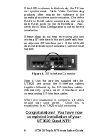
Page 12: ...T1 If the LED continues to blink slowly the TE has not synchronized Note Video Conferencing products often require the software to be operating to achieve synchronization Check the RJ 45 to RJ 45 cable connections and verify both RJ 45 ports for the S T Interface Also verify the S T Bus Configuration is correct for the installation If these steps do not help try moving a known working S T Interfac...

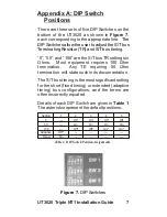
Page 13: ...us timing is the most significant setting for the short fixed timing or extended adaptive timing bus configurations and the terms are often incorrectly equated Details of each DIP Switch are given in Table 1 The asterisks represent the default positions The DIP Switches allow the user to adjust the S T bus Terminating Resistor TR and S T bus timing Setting 0 50 100 Adaptive Fixed 1 Off On 2 Off On...

Page 14: ...re than four terminals can be attached and each terminal must be the same distance away from the NT1 within 10 meters tolerance to a maximum of 200 meters divided by the number of terminals For example two terminals could be 85m and 95m from the NT1 respectively ON OFF From is 200m NT1 to TE Figure 8 Default S T Configuration Alternative Configurations There are three configurations for which the ...

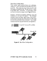
Page 15: ... four terminals arranged as in Figure 9 below Solution Verify the distance between any two terminals is at most 50 meters The farthest terminal must be within 200 meters of the NT1 and it must have its own TR or have a TR wired into the line just before the terminal Up to eight terminals can be supported in this configuration TE with TR From NT1 to last TE is 200m ON OFF Figure 9 Short Bus Configu...

Page 16: ... is within 25 meters from the TR With only one terminal the maximum distance from the NT1 to the TR is 1300 meters The maximum distance is reduced to 1000 meters with two to four terminals as in Figure 10 below A variation of this method called the Y Bus Configuration allows the use of two equally distant TR More details about this configuration are in the next section Y Bus Configuration From NT1...

Page 17: ...aximum of 140 meters from the NT1 within a 10 meter tolerance Each TR can support up to 4 terminals and terminals must be within 25 meters of a TR No TE symmetry is required so one TR can have four terminals connected while the second only has one From NT1 to TR is 140m ON OFF Figure 11 Y Bus Configuration TR TR 11 UT3620 Triple NT1 Installation Guide ...

Page 18: ...n to this information All interfaces described here are located on the rear panel of the UT3620 Table 2 S T Interface Pin Assignments Table 4 Power Connector Pin Assignments Table 3 U Interface Pin Assignments Pin Function Pin Function Pin Function Pin Function 1 3 5 7 2 4 6 8 RX TX RTN TX RX 40V 1 3 5 7 2 4 6 8 RING TIP Pin Function Pin Function 1 40V 2 GND 12 UT3620 NT1 Installation Guide Triple...

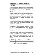
Page 19: ...supply provides up to 40 watts of PS2 power and is used for multiple ISDN Telephones on all lines PS2 power is commonly used to power TE from the NT1 Most data devices such as Video Conferencing units do not require PS2 to function Most ISDN Telephones including those with built in data capabilities require PS2 power The specifications or documentation of the TE will have information on the watts ...

Page 20: ...IP Dual In line Package Hz Hertz ISDN Integrated Services Digital Network m meters MLT Metallic Loop Test NT1 Network Termination type 1 device PS2 Power Source 2 TE Terminal Equipment TR Terminating Resistor V Volts VAC Volts AC VDC Volts DC 14 UT3620 NT1 Installation Guide Triple ...

Page 21: ...f advanced notice isn t practical you will be notified as soon as possible You will be advised of your right to file a complaint with the FCC if you believe it is necessary Your telephone company may make changes in its facilities equipment operations or procedures that could effect the operation of your equipment If they do you will be given advanced notice so as to give you an opportunity to mai...

Page 22: ...ications company cause to request the user to disconnect the equipment User should ensure for their own protection that the electrical ground connections of the power utility telephone lines and internal metallic water pipe system if present are connected together This precaution may be particularly important in rural areas Caution Users should not attempt to make such connections themselves but s...

Page 23: ...NOTES 17 UT3620 Triple NT1 Installation Guide ...

Page 24: ...18 UT3620 NT1 Installation Guide Triple ...

Page 25: ...Wall Mounting Template 4 73 19 UT3620 Triple NT1 Installation Guide ...

Page 26: ......

Page 27: ......

Reviews: