Wiring Instructions
Figure 3
shows the wiring diagram of the
UT3620 with the ISDN TE and the ISDN
U-Interface. Specific step-by-step instructions
follow.
Figure 3.
Interface Wiring Diagram
Video Conferencing Equipment
or ISDN Telephones
U3
U1 U2
S/T1 S/T2 S/T3
40V DC
Power
IS
D
N
S
e
rv
ic
e
3
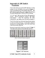
Step 1: Adjust the DIP Switches on the bottom of
the UT3620 for the desired S/T Bus
Configuration. Please refer to Appendix A: DIP
Switch Positions, Page 7, and Appendix B: S/T
Bus Configuration, Page 8, for details.
The manufacturer’s default DIP Switch
configuration will work for a majority of
installations. Adjustments should only be made
if the configuration is an exception as mentioned
in the Appendix B.
UT3620 Triple NT1 Installation Guide
Summary of Contents for UT3620 Triple NT1
Page 1: ...UT3620 Triple NT1 Installation Guide ...
Page 2: ......
Page 23: ...NOTES 17 UT3620 Triple NT1 Installation Guide ...
Page 24: ...18 UT3620 NT1 Installation Guide Triple ...
Page 25: ...Wall Mounting Template 4 73 19 UT3620 Triple NT1 Installation Guide ...
Page 26: ......
Page 27: ......

