42
Alpha 240XP and 240XE - Fault Finding
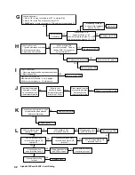
Replace main PCB
Replace coil
Burner output
modulates
NO
NO
YES
YES
Check and correct:-
1. Main PCB - Is plug connected to MET, i.e. Natural Gas
2. Main PCB - Is the RLA plug connected to OFF
3.
- Is wire connected on PCB between terminal 8 and F3
240XP only
G
Volts at Main PCB
across terminals 41, 42
Max. burner press. approx. 10 V DC
Min. burner press. approx. 1.5 V DC
Modulating coil faulty
i.e. correct cold resistance
approx. 40 ohm
J
Overheat thermostat
operated or faulty,
i.e. continuity across
thermostat terminals
Allow to cool.
Continuity across
thermostat terminals
more than 1.5 ohm
Press manual reset on
overheat thermostat.
Continuity across
thermostat terminals
Replace overheat thermostat
NO
YES
NO
K
Continuity across terminals 1 and 3
on reset switch when pressed
(between white wires)
Replace reset switch
Replace ignition PCB
YES
NO
YES
Check and correct:-
1. Ignition electrodes and leads
2. Electrode connections
3. Spark gap and position
H
Is 240V at Main PCB
across terminals 5, 7 and at
Ignition PCB - M1 connector,
across terminals A, C
Air pressure switch proved
YES
YES
Replace ignition PCB
Replace main PCB
NO
NO
Go to section ' ', page 41
E
Replace main PCB
NO
YES
240V at internal clock
terminals 1 and 2
20V DC across clock
terminal 4 and Main PCB
terminal 33
Continuity between clock
terminal 4 and Main PCB
terminal 1
20V DC across Main PCB
terminals 1 and 33
L
240V at Main PCB
terminals 27 and 28
Wiring between clock
and PCB is correct
YES
YES
NO
YES
Continuity across
clock terminals 3 and 4
Internal clock calling
for heat
Wiring between clock
and PCB is correct
Replace clock
Check external controls
are calling for heat
YES
NO
YES
NO
YES
YES
YES
Check and correct:-
1. Flame sensing electrode and lead connections
2. Electrode position
Flame current should be:-
Maximum burner pressure - 3.5 mA approx.
Minimum burner pressure - 1.5 mA approx.
I
Replace ignition PCB
Summary of Contents for Alpha 240XE
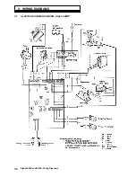
Page 35: ...35 Alpha 240XP and 240XE Wiring Diagrams 9 2 ILLUSTRATED WIRING DIAGRAM Alpha 240XE ...
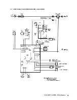
Page 36: ...36 Alpha 240XP and 240XE Wiring Diagrams 9 3 FUNCTIONAL FLOW WIRING DIAGRAM Alpha 240XP ...
Page 37: ...37 Alpha 240XP and 240XE Wiring Diagrams 9 4 FUNCTIONAL FLOW WIRING DIAGRAM Alpha 240XE ...

