31
Instructions for the installer
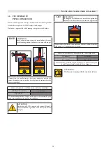
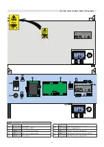
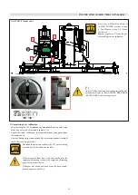
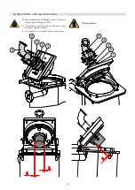
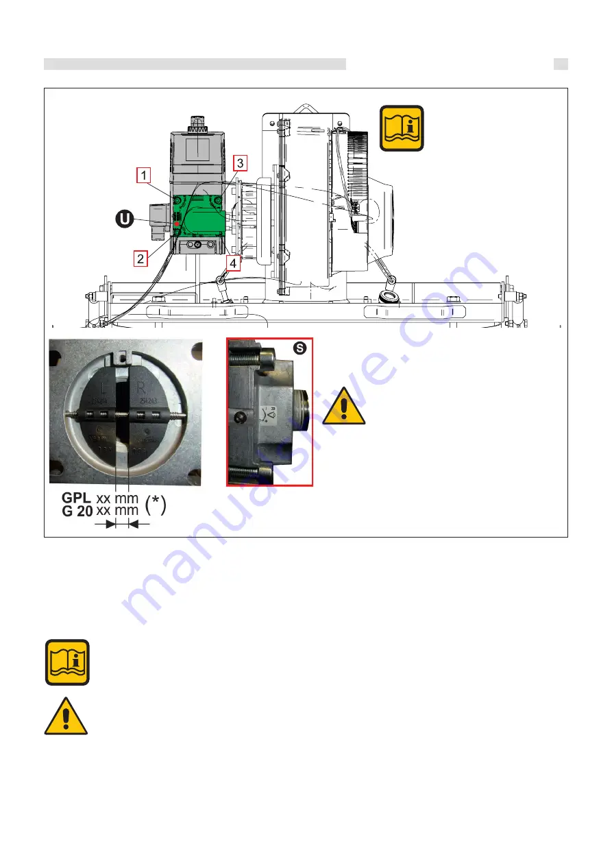
GAS VALVE (Front view)
Note: If it is difficult to adjust it
to MAX POWER, remove screws
1 - 2 and loosen screws 3 - 4 (5 mm
Allen key).
Remove regulator U from the gas
valve and operate as indicated.
(*)
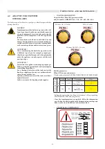
Adjust VG
fl
ue adjusting device opening to the val-
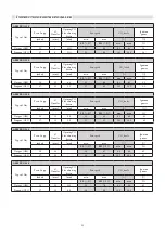
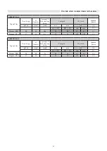
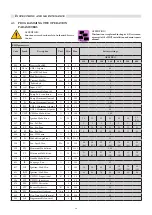
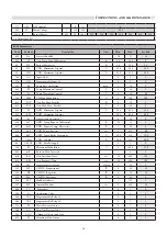
ues indicated (refer to the NOZZLES - PRESSURES
- FLOW RATES tables) using screw S.
3) Completing basic calibration
- a
ft
er checking the CO
2
minimum and maximum
flo
w rate values and
made any necessary adjustments (points 1-2):
- disable the timed “calibration” function by disconnecting power from
the main switch.
- close the
fl
ue gas inspection outlet of the intake and exhaust terminal
- check there are no gas leaks.
For smooth operation, calibrate the CO
2
values taking
care to observe the values in the table.
If the measured
flo
w rate is too low, make sure the
supply and draining systems (the supply and draining
pipes) are not obstructed.
If they are not obstructed, make sure the burner and/
or exchanger are not dirty.
Summary of Contents for ARES Pro 150
Page 2: ......


