Chapter 2 Installation and Wiring
15
Category
Terminal
label
Name
Description of
terminal function
Specification
Encoder
input
Z+
、
Z-
Encoder power
and signal input
Encoder Z-phase
input
Standard RS422
,
Maximum 300KHZ
,
Compatible with 5 v OC
interface.
Encoder
output
OA+
、
OA-
Encoder signal
output
Encoder A-phase
output
1:1 divider feedback to
the system
,
Standard
RS422
OB+
、
OB-
Encoder B-phase
output
OZ+
、
OZ-
Encoder Z-phase
output
Pulse
input
D+
、
D-
Pulse command
input
CW/Directional
signal /B-phase
input
Standard RS422, the
parameterchoose the
pulse command input
mode.
2.5.2 Wiring of Control Circuit Terminals
●
Wiring of Analog Input Terminals
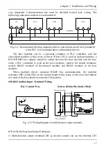
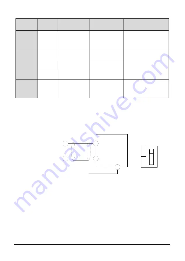
AI1 terminals accept analog signal input, DIP switch SW1 select the input voltage (0 ~
10V) or the input current (0 ~ 20mA). The wiring of terminals is shown in Fig. 2-8:
Fig. 2-8 Wiring diagram of analog input terminals
●
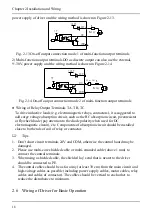
Wiring of Analog Output Terminal
Analog output terminal AO1 is only support the voltage signal output, external
connecting analog meter can indicate a variety of physical quantities. The wiring of
terminals is shown in Fig. 2-9:
AI1 0~10V/0~20mA
AI1
GND
PE
Near-end of
shield line is
grounded
I
V
SW1
Driver
Summary of Contents for AS600M Series
Page 96: ...96 ...


