Chapter 3 Operation
21
3.1.1 Keypad Layout
PRG
ESC
>>
ENTER
JOG
RUN
FWD
REV
TRIP
REMOTE
r/min
m/s
%
A
V
Hz
-
+
RUN
STOP
RESET
Four-digit digital
tube display
Programming
Shift
Running-state LCDs
Run
Increase of digital encoder
Jog/
Direction switch key
Stop/Reset
Unit of frequency: Hz
Unit of current: A
Unit of voltage: V
Rotate speed: r/min
Line speed: m/s
Decrease of digital encoder
Enter
Percentage: %
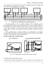
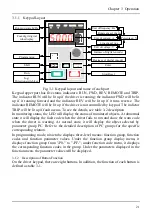
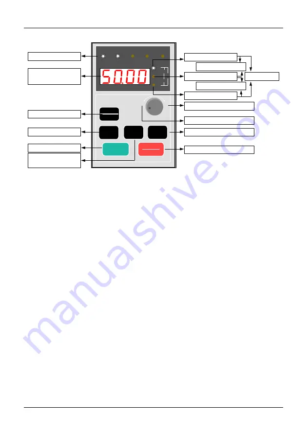
Fig. 3-1 Keypad layout and name of each part
Keypad upper part has five status indicators: RUN, FWD, REV, REMOTE and TRIP.
The indicator RUN will be lit up if the driver is running; the indicator FWD will be lit
up if it running forward and the indicator REV will be lit up if it runs reverse. The
indicator REMOTE will be lit up if the driver is not controlled by keypad. The indictor
TRIP will be lit up if fault occurs. To see the details, see table 3-2 description.
In monitoring status, the LED will display the status of monitored objects. At abnormal
state it will display the fault code when the driver fails to run and show the warn code
when the driver is warning. At normal state, it will display the object selected by
parameter group PC. Refer to the detailed description of PC groups for the specific
corresponding relation.
In programming mode, nixie tube displays three-level menus: function group, function
codes and function parameter values. Under the function group display menu, it
displays function group from "-P0-" to "-PF-"; under function code menu, it displays
the corresponding function codes in the group. Under the parameters displayed in the
function menu, the parameter values will be displayed.
3.1.2 Description of Button Function
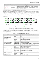
On the driver keypad, there are eight buttons. In addition, the function of each button is
defined as table 3-1.
Summary of Contents for AS600M Series
Page 96: ...96 ...


