Chapter 3 Operation
24
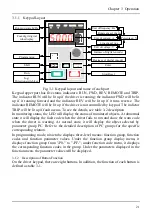
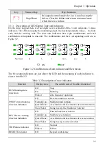
Indicator
Display state
The current state of the driver indicated
(Exclusive for control
keypad)
On
Terminal control state
Flicker
Serial communication state
3.1.4 Operation Method of Keypad
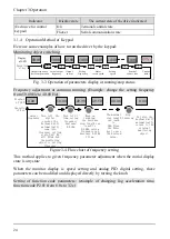
Here are some examples of how to run the driver by the keypad:
Monitoring object switching:
50.00
45.00
50.00
1440
1440
>>
>>
>>
>>
>>
>>
50.00
Display
of LED
Operation
of key
>>
Actual output
frequency
Output frequency
before compensation
Output
current
Setting
frequency
Motor
rotate speed
Setting
speed
Terminal
status
External
count value
1000
Fig. 3-3 Operation of parameters display at running/stop status
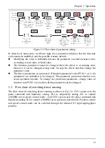
Frequency adjustment at common running: (Example: change the setting frequency
from 50.00 Hz to 40.00 Hz)
0.00
50.00
49.99
49.50
output
frequency
Turn left the
digital
encoder,the
keyboard will
automatically
come into
frequency setting
state.Unit Hz
will blink.And
the monitoring
object is setting
frequency
Turn left 1
time,seting
frequency
decrease
0.01Hz
Keep on
turnning,
the decrease
step length can
reach to
0.10Hz,seting
frequence can
decrease 0.10Hz
1 time.
The maximal
step length
can reach
to
1Hz.Press
the Enter
key to save
the desired
value.
40.00
3s later,the
keyboard will
automatically
return to the
original
monitoring
object.
0.00
-
-
-
-
Stop
turnning
Display
of LED
Operation
of key
Figure 3-4 Flow chart of frequency setting
This method applies to given frequency parameter adjustment when the initial display
state is any state.
When the monitor display is speed setting and analog PID digital setting, these
parameters can be modified and displayed directly by turning the knob.
Setting of function code parameters: (example of changing Jog acceleration time,
function code P2.01 from 6.0s to 3.2s)
Summary of Contents for AS600M Series
Page 96: ...96 ...


