Chapter 5 Detailed Function Introduction
53
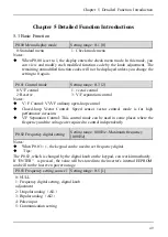
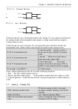
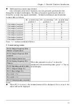
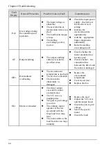
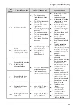
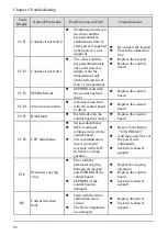
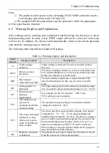
P3.15 = 0 Forward / Reverse
X1(Forward)
X2(Reverse)
Forward
Reverse
Stop
P3.15 = 1 run + direction
X1( run)
X2(direction)
Forward
Reverse
Stop
When the speed is up to the bipolar analog to the timing, X1 runs signal, the polarity of
the analog decides the running direction ,positive voltage means forward, negative
voltage means reverse.
When the speed is up to the pulse, X1 runs signal, the pulse direction decides the
running direction,
positive pulse means forward, negative pulse means reverse.
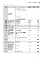
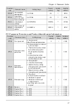
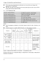
P3.20 Y1 terminal function
3: Speed reached Speed to reach a
given speed range within P3.26 output
valid
P3.21 Y2 terminal function
2: Ready When the inverter has no
fault, and ready output valid
P3.22 Y3 terminal function
4: Exact stop place Exact stop
position deviation in the range of P6.15
and P6.16 time after the effective output
P3.24 relay 1 (TA/TB/TC)
19: Fault output
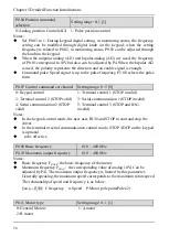
Notes: Output terminals can also be set to the following functions
1
:
Run the drive enable output is active
5
:
Speed / position status output In the position control mode, the output is valid
7:
0 speed operation When the driver hasn’t any speed output, the terminal output is
valid
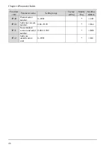
5.3 Analog (Group P4)
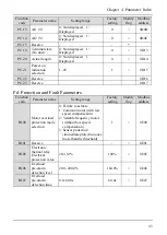
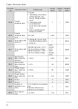
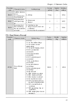
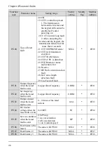
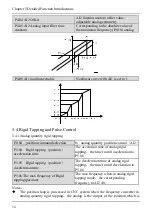
P4.01 Analog zero drift value
When the analog at below this range,
treated as zero(the absolute value of the
bipolar)
P4.02 AI1 Offset
AI1 (unipolar analog) Offset
P4.03 AI1 maximum analog input
value
Value corresponds to the maximum
frequency (P0.10) analog
Summary of Contents for AS600M Series
Page 96: ...96 ...

