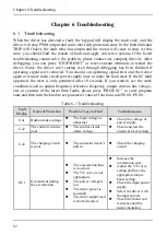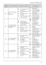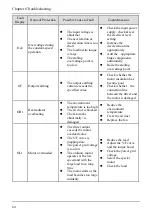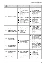
Chapter 8 Maintenance
76
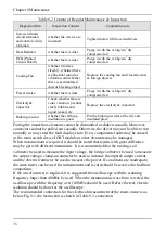
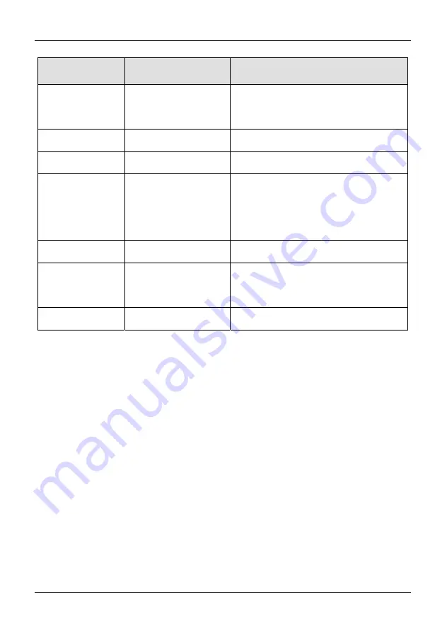
Table 8-2 Content of Regular Maintenance & Inspection
Inspection Item
Inspection Content
Countermeasure
Screws of main
circuit terminals
and control circuit
terminals
whether the screws are
loosened
Tighten them with the screwdrivers
Heat Radiator
whether there is dust
Purge it with the 4~6kg/cm
2
dry
compressed air
PCB (Printed
Circuit Board)
whether there is dust
Purge it with the 4~6kg/cm
2
dry
compressed air
Cooling Fan
whether it rotates
flexibly, whether there
is abnormal sound or
vibration, and whether
there is accumulated
dust or blocking object
Replace the cooling fan and clear the dust
& foreign objects
Power device
whether there is dust
Purge it with the 4~6kg/cm
2
dry
compressed air
Electrolytic
Capacitor
Check whether there is
color variation, peculiar
smell, bubbles and
liquid leaked, etc.
Replace the electrolytic capacitor
Braking resistor
whether the earthing
insulation is good
Put the braking resistor at the dry and
insulated place
During the inspection, elements cannot be dismantled or shaken casually. Moreover,
connectors cannot be pulled out casually. Otherwise, the driver may not be able to run
normally or may enter the fault display state. Even, components faults may be caused
or the main switch device IGBT module or other elements may be damaged.
When measurement is required, it should be noted that results with great difference
may be got with different instruments. It is recommended that the moving-coil
voltmeter be used to measure the input voltage, the bridge voltmeter be used to measure
the output voltage, clamp-on ammeter be used to measure the input & output current,
and the electric wattmeter be used to measure the power. If conditions are inadequate,
the same meter can be used for measurement and record should be reserved to facilitate
comparison.
If the waveform test is required, it is suggested the oscilloscope with the scanning
frequency larger than 40MHz be used. When the instantaneous waveform is tested, the
oscilloscope with the frequency over 100MHz should be used. Before the test, electric
isolation should be done for the oscilloscope.
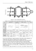
The recommended connection for the electrical measurement of the main circuit is as
below Fig 8-1, the instruction is shown in Table 8-3.connection
Summary of Contents for AS600M Series
Page 96: ...96 ...

