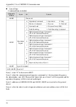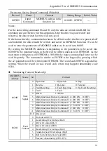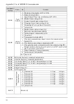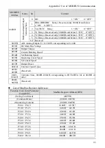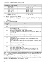
Appendix 2 Use of MODBUS Communication
83
(2) Shielded cables should be used as the communication cables. The shielding layer
should be connected to the earthing terminal of driver, while the other end will
not be connected. (To prevent malfunction caused by disturbance)
The sequence to have communication with PLC is as follows:
1. When the power supply is cut off, connect the communication cable between
PLC and driver.
2. Supply the power.
3. Set the parameters required by communication on the keypad (P0.03~P0.07).
4. Cut off the power supply and wait until keypad display disappears completely.
5. Switch on the power supply again.
6. Conduct the communication with PLC.
Setting of Communication Parameters
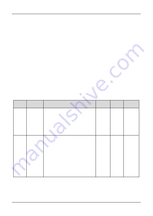
To communicate with PLC, communication-related parameters should be set. All the
parameters cannot be changed during running except for Pb.01 and Pb.04 and can be
changed during stop state. Pb.01 and Pb.04 can be changed during driver running.
“
○
” means that the parameters can be changed during inverter running and stop state;
“×” means that the parameters cannot be changed during running;
Function
code
Parameter
name
Setting range
Factory
setting
Modify
flag
Modbus
address
P0.03
Speed
command
selection
0: NULL
1: Frequency digital setting, digital
knob adjustment
2: Unipolar analog
(
AI1
)
3: Bipolar Analog
(
AI2
)
4: Pulse input
5: Communication setting
1 ×
0002H
P0.07
Control
command
set
channel
0: Keypad control
1: Terminal control 1 (STOP key is
inactive)
2: Terminal control 2 (STOP key is
enabled)
3: Serial communication 1 (STOP
key is inactive)
4: Serial communication 2 (STOP
key is enabled)
5: Terminal control 3 (STOP and
JOG keys are inactive)
0 ×
0001H
*Note 1: Only when the “Communication setting” passage is selected, can the
command be written into the corresponding register. Otherwise, 02h will be reported.
*Note 2: If the Baud rate selection and the parity check selection are revised, new
setting will not become effective until the driver is stopped first and then restarted.
Summary of Contents for AS600M Series
Page 96: ...96 ...

