background image

33

3 Operation

Alpha Technologies

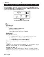
Low Battery Shutdown

This red LED turns on when the battery voltage is 12% below nominal. The unit automati-
cally shuts itself down and no longer provides power to the loads to prevent
overdischarge damage to the batteries.

Test

This yellow LED shows the unit is in self test mode (Section 3.3). If it fails the test, the
Service LED is on and the unit defaults to Line Present operation. You should do trouble-
shooting as shown in Sections 3.4 or 5.2.

TIP:

 At start-up, this LED flashes for about 5 to 15 seconds.

Line Synchronization

If both the:

• Line Present

• Line Failure

LEDs are on, the unit is synchronizing its output with the input before starting Line
Present operation. This takes about 15 seconds.

Push Buttons

Alarm Off

This turns off most audible alarms. It stays off until another alarm occurs.

TIP:

 Some alarms, such as Line Failure, cannot be turned off and will continue to sound

every 20 seconds. If the Service LED is on, press and hold down the Alarm Off switch
and note which Output Load LEDs turn on or flash (Section 3.4).

Manual Start

This starts the unit with battery power when line power is absent or unqualified.

It can also be used as a self test. If the Line Present LED is on, press it for 5 seconds.
This tests the inverter and batteries for one minute by providing backup battery power to
the loads, returning to line present mode when done.

3.5 Controlling the Unit With the Standard Interface Device (SID) (Continued)

Summary of Contents for CFR 5000

Page 1: ...CFR 5000 5000RM Uninterruptible Power Supplies From Alpha Technologies Operator s Manual...

Page 2: ...Operator s Manual CFR 5000 CFR 5000RM Uninterruptible Power Supplies Alpha Technologies...

Page 3: ...sed in a commercial environment If there is interference to radio or TV reception which is determined by switching it on and off relocate the equipment or use an electrical circuit other than the one...

Page 4: ...he load s is compatible with the unit s output Also see the line voltage and current is compatible with theunit sinputrequirements The unit should be installed on a dedicated circuit Wiring should be...

Page 5: ...e quired When batteries are in storage charge them at least once every three months for optimum performance and to extend their lifetime Always replace batteries with ones of identical type and rating...

Page 6: ...eration 27 3 1 Turning On the Unit 28 3 2 Turning Off the Unit 29 3 3 Testing the Unit 30 3 4 Troubleshooting With the SID 31 3 5 Controlling the Unit With the Standard Interface Device SID 32 4 Commu...

Page 7: ...section introduces you to the CFR 5000 and CFR 5000RM UPS s The CFR series many advantages Section 1 1 An unpacking and inspection checklist Section 1 2 An tour of the units their connectors switches...

Page 8: ...erro resonant transformer provides non degradable spike and surge protection Extended Backup Capability Alpha s EBP Series external battery packs extends backup time during power outages Installing th...

Page 9: ...turn the unit for servicing pack it in the original shipping container Alpha is not responsible for damage caused by the improper packagingofreturnedunits Read This Manual Before installation become f...

Page 10: ..._______________________________ Fax ____________________________________ E Mail ___________________________________ For emergency technical support 7 days a week 24 hours a day call USA 1 800 863 3364...

Page 11: ...the Standard Interface Dis play SID Section 3 5 or the optional Intelligent Interface Device IID Alpha manual 018 029 B0 001 Cover The cover can be removed to allow access to the unit s interior in or...

Page 12: ...the Standard Interface Display SID Section 3 5 or the optional Intelligent Interface Device IID Alpha manual 018 029 B0 001 Fans These four fans cool the unit They must not be blocked ALARM OFF MANUAL...

Page 13: ...r Panels CFR 5000RM Fans These fans cool the unit They must not be blocked Output Connector These plates are the unit s output power con nector It is factory configured to your specifi cations See Sec...

Page 14: ...ngle point ground connec tion Always follow your local electrical code for correct grounding This connector grounds the external EBP battery packs to the unit Battery Circuit Breaker This protects the...

Page 15: ...B 9 port provides dry contact status monitoring and output shutdown capability via LAN communication Section 2 7 External IID An external IID plugs into this connector for remote control and monitorin...

Page 16: ...ack and install the unit Section 2 2 How to connect the unit to the loads and the line Section 2 3 How to connect the external battery packs Section 2 4 How to connect the external alarm port Section...

Page 17: ...know a UPS is in the building Label the service panel s to identify the circuit s supplying and being supplied by theunit 2 1 2 Grounding Utility Line All wiring should be done only by qualified pers...

Page 18: ...rical code when installing or sizing circuit breakers 2 1 3 Standby Generator The unit has frequency sense circuits for operation with most standby generators Use a generator equipped with electronic...

Page 19: ...ench Procedure 1 The unit is shipped attached to a pallet Use a forklift or pallet jack to transport the unit and pallet to the installation site 2 Remove the packing from around the unit Unbolt the u...

Page 20: ...angerous voltages inside the unit when the cover is removed 2 When removing or attaching the cover do not let it touch the battery terminals battery wires or other internal components 7 Reattach the c...

Page 21: ...225 lbs 102 kg Screwdriver or power screwdriver with a Philips bit Procedure 1 The unit is shipped attached to a pallet Use a forklift to transport the unit and pallet to the installation site 2 Unscr...

Page 22: ...the unit s AC line cord into the receptacle Figure 2 1 3 If used plug in an external battery pack Section 2 4 TIP The rackmount unit has no internal batteries It uses an external battery pack 4 Switch...

Page 23: ...Pounds 2 3Nm Switch on the utility circuit breaker supplying power to the unit Make sure the unit has been wired correctly by measuring the voltages at the terminal block Switch off the circuit breake...

Page 24: ...nd frequency ratings for the unit as shown on the nameplate Figure 2 4 Output Terminal Block Wiring TIP Over current protection for theAC output circuit must be provided when the unit is installed y c...

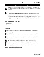
Page 25: ...a battery s voltage varies more than 0 3 VDC from the others do not use it Tools and Materials Required DC voltmeter Phillipsscrewdriver Procedure 1 Verify the battery circuit breaker is switched off...

Page 26: ...ation 20 Alpha Technologies 2 4 Connecting the External Battery Pack Continued Figure 2 6 Connecting an External Battery Pack to the 5000 4 5 2 Figure 2 5 Connecting an External Battery Pack to the 50...

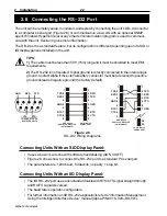
Page 27: ...ecommended The connecting cable can be twisted or shielded wire not more than 100 ft long The contacts must be shorted for at least 1 5 seconds with unit shutdown about 2 seconds aftertheshortingstart...

Page 28: ...egative ground the factory default Connecting Units With an SID Display Panel It uses a basic 3 wire line with software handshaking XON XOFF Figure 2 8 shows how to connect the RS 232 port to a standa...

Page 29: ...ection to the unit s mi croprocessor shuts down the unit s output The shutdown delay duration and recovery is con trolled via RS 232 commands Section 4 5 Figure 2 9 Wiring the LAN Port 8 7 6 5 4 3 2 1...

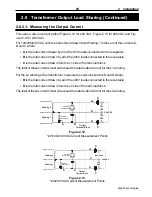
Page 30: ...are two ways to calculate the current drawn by the loads measuring or displaying the output current 230 VAC 120 VAC 120 or 88 VAC 208 VAC 240 VAC L1 NEUTRAL NEUTRAL FERRO TRANSFORMER 240 or 208 VAC 3...

Page 31: ...the rated output current for the L1 winding For the L2 winding of the transformer measure the currents at points B and D where B is the total current drawn by all of the 240V loads connected to the re...

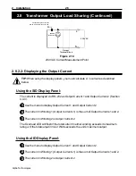
Page 32: ...is the sum of Output Currents 1 and 2 3 The current in Winding 2 is Output Current 2 The Overload LED will flash if the total current in either winding exceeds its maximum rating or if the total outp...

Page 33: ...to operate the CFR 5000 and CFR 5000RM UPS s How to turn the unit on and off Sections 3 1 3 2 How to start the unit s self test Section 3 3 How to troubleshoot the unit with the SID Section 3 4 How to...

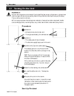
Page 34: ...y circuit breakers 2 Switch on The utility panel s main breaker The breaker supplying power to the unit 3 Switch on the input circuit breaker The display panel s Line Present LED turns on to show the...

Page 35: ...ility circuit breaker DANGER During servicing place a warning notice on the circuit breaker supplying the unit Shutdown Finished Cold Start Procedure This starts the unit with battery power when line...

Page 36: ...Present LED must be on Procedure 1 Press the Manual Start button down for 5 seconds During the test the Test Line Present and Line Failure LEDs are on for about one minute 2 If a fault is found the un...

Page 37: ...s a l F g n i h s a l F g n i h s a l F g n i h s a l F g n i h s a l F h g i h e g a t l o v t u p t u O s e i g o l o n h c e T a h p l A t c a t n o C 0 5 0 5 0 5 0 5 0 5 N ON ON ON ON O e r u l i...

Page 38: ...than 10 or less than 20 of nominal voltage The line frequency is outside of 3Hz of the nominal frequency The unit is providing backup battery power to the loads TIP Also see Low Battery Warning and Lo...

Page 39: ...onizing its output with the input before starting Line Present operation This takes about 15 seconds Push Buttons Alarm Off This turns off most audible alarms It stays off until another alarm occurs T...

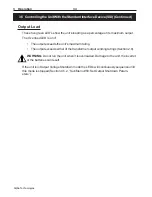
Page 40: ...LED is on if The output exceeds the unit s maximum rating The output exceeds either of the transformer output winding ratings Section 2 8 WARNING Do not run the unit when it is overloaded Damage to th...

Page 41: ...ction 4 1 How to understand and use the opening menu Section 4 2 A description of the menu tree Section 4 3 Descriptions of the system input and output and battery parameters menus Section 4 4 Descrip...

Page 42: ...Com 1 is used and the unit is called CFR Procedure 1 The path is Start Programs Accesso ries Communications HyperTerminal 2 Click on the Hypertrm exe icon The Connection Description screen appears Fig...

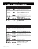
Page 43: ...erminal Set Up Finished Figure 4 4 Opening Menu in CFR Screen ALPHA TECHNOLOGIES CFR OPENING MENU 1 SYSTEM PARAMETERS 2 INPUT PARAMETERS 3 OUTPUT PARAMETERS 4 BATTERY PARAMETERS 5 USER PARAMETERS 6 NO...

Page 44: ...ect changes in the unit s status To update it type in the number and press Enter For many functions you need to enter a password The factory set password is 1111 If you change the password Item 58 mak...

Page 45: ...n e e r c S n o s w o h S n e e r c S n o s w o h S n e e r c S n o s w o h S n e e r c S n o s w o h S n e e r c S n o s w o h S e s u a C e s u a C e s u a C e s u a C e s u a C y r e t t a B w o L...

Page 46: ...c a t n o C t l u a f a s a h t i n u e h T y c n e g r e m E y c n e g r e m E y c n e g r e m E y c n e g r e m E y c n e g r e m E f f O r e w o P F F O P Y C N G M E F F O P Y C N G M E F F O P Y...

Page 47: ...rrent Charger Status Temperature 5 User Parameters 50 Output Shutdown Setup 52 External Modem Setup 53 Set Test Start DD HH MM 00 00 00 55 Set Test Frequency off 56 Transmit UnsolicitedAlarms 58 Set U...

Page 48: ...n I s r e t e m a r a P t u p n I e g a t l o V e g a t l o V e g a t l o V e g a t l o V e g a t l o V s t l o V X X X e g a t l o v s e n i l e h T t n e r r u C t n e r r u C t n e r r u C t n e r...

Page 49: ...e g a t l o v L d n a N n e e w t e b e n o d s i t n e m e r u s a e m t i n u e h t f o e d i s C A V 0 4 2 r o 8 0 2 e h t r o f e g a t l o v t u p t u o S M R e u r t e h t s i 2 e g a t l o v t...

Page 50: ...g r a h c s i h t n i d e d u l c n i s i e g a t l o v r i e h t d e h c a t t a e r a s k c a p y r e t t a b l a n r e t x e f I t n e m e r u s a e m t n e r r u C t n e r r u C t n e r r u C t n...

Page 51: ...i t c e S 2 52 52 52 52 5 l a n r e t x E p u t e S m e d o M n i d e n i a l p x e s i e s u s u n e m s i h T t i n u e h t o t m e d o m l a n r e t x e n a t c e n n o c o t u o y s w o l l a s i...

Page 52: ...r e t e m a r a P r e s U d e u n i t n o C s r e t e m a r a P r e s U d e u n i t n o C s r e t e m a r a P r e s U d e u n i t n o C s r e t e m a r a P r e s U 6 56 56 56 56 5 t i m s n a r T d e...

Page 53: ...r p s i e n i l e h t n e h w y l n o s e m u s e r t u p t u o e h t S E Y o t t e s f I r o t n e s e r p t o n s i e n i l e h t f I d e h s i n i f s i n w o d t u h s e h t r e t f a s e m u s e...

Page 54: ...e g n a h c s u t a t s s t i n u e h t s e g a s s e m e h t e r a g n i w o l l o f e h T p u r e w o P 0 0 0 S P U e c n a r e l o t f o t u o t u p n I 1 0 0 S P U t u o k c a l b t u p n I 2 0 0...

Page 55: ...a 5 75 75 75 75 7 i H t c e t e D w o l S f e R e c n a b r u t s i d e n i l e d u t i l p m a h g i h w o l s a o t e v i t i s n e s e r o m t i n u e h t s e k a m s i h t g n i s a e r c n I y b...

Page 56: ...al up the CFR for remote monitoring or control Once connected all RS 232 menus are accessible Equipment and Settings Equipment An external modem US Robotics Sportster 1200 9600 19 2K or 28 8K baud or...

Page 57: ...e not using a US Robotics Sportster set Custom Init cmd Item 527 to the values your modem uses Step 2 Connect and Configure the Modem 3 iv If you have more than one unit set the Location ID Item 526 t...

Page 58: ...S h c t i w S P I D m e d o M s g n i t t e S h c t i w S P I D m e d o M s g n i t t e S h c t i w S P I D m e d o M s g n i t t e S h c t i w S P I D m e d o M s g n i t t e S h c t i w S P I D m e...

Page 59: ...data all the time I0 Disable software data flow control no Xon Xoff flow control B1 Set the RS 232 serial port rate to fixed set modem to detect the AT command baud rate and maintain it The first thre...

Page 60: ...e After starting one of the modem options This guarantees the modem is initialized before sending out the first automatic alarm If initalization fails the CFR assumes the modem is on line sends an esc...

Page 61: ...is when the modem replies with a connect message in less than 60 seconds The CFR stores alarm messages in a buffer that holds up to 7 messages When the modem is operating it sends the alarms out in th...

Page 62: ...o i t c a t a h w s e i f i c e p s u n e m s i h T e r a s n o i t c a e l b i s s o p e e r h t t n e v e e h t e r o n g i n o i t c a o n e k a T E N O N t n e v e e h t t r o p e r d n a r e b m...

Page 63: ...2 5 2 l a i D t e S r e b m u N e n o h P e n o h p e h t n e h t d n a T D T A h t i w t r a t s d l u o h s g n i r t s e h T r e b m u n e n o h p 2 l a i D e h t s t e s s i h T s n o i t c u r t...

Page 64: ...battery backup time Section 5 1 How to troubleshoot the unit Section 5 2 How to return the unit to Alpha for repair Section 5 3 How to replace the CFR 5000 s internal batteries Section 5 4 How to chan...

Page 65: ...test so the batteries are fully charged Do a self test first Section 3 3 If it passes do this test If it doesn t find out why before proceeding For reference compare your measured time to the times li...

Page 66: ...backup power may increase by up to 20 Once at this peak they slowly loose capacity and eventually cannot provide backup power m o t p m y S m o t p m y S m o t p m y S m o t p m y S m o t p m y S e s...

Page 67: ...r o h g i h o o t e g a t l o v e n i L e z i l i b a t s o t e g a t l o v r o f t i a W n o i t a z i n o r h c n y s n i s i t i n U e d o m e t u n i m 1 t u o b a t i a W n o D E L e c i v r e S...

Page 68: ...d e t i n U s e t a t S d e t i n U s e t a t S d e t i n U s e t a t S d e t i n U 0 6 3 2 7 4 6 0 6 3 a d a n a C 6 7 4 1 0 3 4 4 0 6 m o d g n i K d e t i n U 0 1 1 2 2 4 9 7 2 1 4 4 y n a m r e G...

Page 69: ...all loads 4 If an external battery pack is connected dis connect it 5 Loosen the two Phillips screws on the front panel 6 Carefully pull the lower part of the front panel away from the unit and then l...

Page 70: ...ltage by 3 The voltage should be between 54 VDC to 57 VDC If it is switch off the Input circuit breaker and disconnect the utility line If it is not the charger is faulty ContactAlpha Technologies cus...

Page 71: ...traps first and attach them last to reduce the chance of sparking 1 Disconnect 1 The copper straps 2 Thebatteryconnectionwires 3 Thein linefuse 5 4 Replacing the Internal Batteries Continued Red Batte...

Page 72: ...ry retaining bars and remove them Remove the top batteries first then the bottom two batteries 3 Starting at the bottom install the new batteries 4 Reinstall the battery retaining bars 5 Rewire the ba...

Page 73: ...before starting this procedure Tools and Materials Required If reconfiguring from 208 240 VAC to 120 VAC the 30 Amp input circuit breaker must be replaced with a 50 Amp circuit breaker Contact Alpha T...

Page 74: ...put Terminal Block 1 Find the input terminal block which is on the right hand side of the unit when you are facing the batteries 2 On the side of the battery compartment is a chart showing how to conf...

Page 75: ...nectors as shown in the diagram below Ground Stud 120 VAC Neutral 208 VAC 240 VAC 2 Wire the output connector s to the output voltage you need 3 Reattach the cover and the front panel 4 Turn on the un...

Page 76: ...uit breakers on the rear panel are switched off 2 Remove the top panel 3 Find the main board labeled as 700 255 xx on the top right hand side of the interior when you are facing the rear panel 4 Recon...

Page 77: ...which is mounted in front of the main board as you are facing the rear panel Rear Panel Input Terminal Block 2 If needed configure the terminal block to the input voltage you are using as shown below...

Page 78: ...2 3 4 1 2 3 4 120 VAC Output Transformer This Way 208 VAC Output 240 VAC Output 120 N 120 N 120 N 208 240 To Output Receptacles To Output Receptacles Rear Panel This Way 2 If needed configure the out...

Page 79: ...5 2 1 5 2 1 5 2 1 5 2 2 6 2 2 6 2 2 6 2 2 6 2 2 6 3 3 7 3 3 7 3 3 7 3 3 7 3 3 7 5 4 8 5 4 8 5 4 8 5 4 8 5 4 8 8 5 9 8 5 9 8 5 9 8 5 9 8 5 9 0 0 1 0 0 1 0 0 1 0 0 1 0 0 1 0 4 3 3 0 4 3 3 0 4 3 3 0 4 3...

Page 80: ...t l o V t u p n I n o i t a i r a V e g a t l o V t u p n I C A V 0 1 o t 0 2 z H y c n e u q e r F t u p t u O z H y c n e u q e r F t u p t u O z H y c n e u q e r F t u p t u O z H y c n e u q e r...

Page 81: ...R 5000RM Alarms On Display Panel 32 34 Alarms RS 232 39 40 Battery Backup Time Measuring 59 Battery Charger Test 64 Battery Circuit Breaker 8 Changing Input Output Voltage 67 72 Computer Connection an...

Page 82: ...ith 30 Troubleshooting With 31 Using 32 34 E Electromagnetic Radiation from Unit 28 Electrically Noisy Devices Connection of 11 Emergency Power Off Switch 21 Emergency Shutdown Procedure Inside Rear C...

Page 83: ...unications Menu Tree RS 232 41 Modem External See RS 232 Communications Monitoring Remote See Remote Monitoring Mounting to Floor 13 14 N No Line Starting Unit With 29 O Odors given off by unit 28 On...

Page 84: ...rgency Power Off Switch 21 How Unit Shows A Shutdown 34 Normal 29 Output Shutdown via RS 232 46 47 SID Display Panel 32 Specifications 74 Battery Run times 73 Standby Generator use of 12 Starting Turn...

Page 85: ...anges 11 Input Output Measuring via RS 232 See RS 232 Communications W Warnings Labels on Utility Panel Placing 11 Line Failure 32 Low Battery 32 33 Malfunction 32 No Utility Line 32 RS 232 See RS 232...

Page 86: ...unit has been damaged due to one of these causes or if the unit is free of defects a handling or repair fee may be assessed prior to returning the unit WITH RESPECT TO BATTERIES PERIPHERAL DEVICES ATT...

Page 87: ...7 2 1 4 4 y n a m r e G y n a m r e G y n a m r e G y n a m r e G y n a m r e G 0 9 8 8 9 7 2 2 1 9 9 4 t s a E e l d d i M 5 7 6 5 7 3 5 2 7 5 3 a i l a r t s u A 0 2 3 3 2 2 7 9 2 1 6 Emergency Shu...

Page 88: ...l 604 430 1476 Fax 604 430 8908 Alpha Technologies Cartel Business Estate Edinburgh Way Harlow Essex CM20 2TT UK Tel 44 1279 422110 Fax 44 1279 423355 Alpha Technologies GmbH Hansastrasse 8 D 91126 Sc...

Reviews: